CAUTION:
Before servicing this chassis, it is important that the service technician read the "Safety
Precautions" and "Product Safety Notices" in this service manual.
ATTENTION:
Avant d'effectuer l'entretien du châassis, le technicien doit lire les «Précautions de sécurité»
et les «Notices de sécurité du produit» présentés dans le présent manuel.
VORSICHT:
Vor Öffnen des Gehäuses hat der Service-Ingenieur die ,,Sicherheitshinweise" und ,,Hinweise
zur Produktsicherheit" in diesem Wartungshandbuch zu lesen.
SERVICE MANUAL
MANUEL D'ENTRETIEN
WARTUNGSHANDBUCH
Data
contained
within
this
Service
manual is subject to alteration for
improvement.
Les données fournies dans le présent
manuel d'entretien peuvent faire l'objet
de modifications en vue de perfectionner
le produit.
Die
in
diesem
Wartungshandbuch
enthaltenen Spezifikationen können sich
zwecks Verbesserungen ändern.
SPECIFICATIONS AND PARTS ARE SUBJECT TO CHANGE FOR IMPROVEMENT
Monitor
November 2004
No. 0423
CPX1403MS
2
SERVICE
MANUAL
1. Precautions --------------------------------- 3
1-1. Safety Precautions --------------------- 3
1-2. Servicing Precautions ----------------- 5
1-3. Precautions for Electrostatically
Sensitive Devices(ESDs) ---------------- 6
2. Specifications ------------------------------ 7
3. Description of Controls ----------------- 9
4. Alignment and Adjustments ---------- 10
4-1. Preadjustment -------------------------- 10
4-2. Factory/Service Mode ---------------- 10
4-3. Other Adjustments --------------------- 12
5. Using Devices and Description ------ 17
5-1. Main Signal Processor(VDP3130Y) -- 17
5-2. Vertical Output(LA78040) ------------ 20
5-3. Video Output Amplifier
(TDA6108JF) ------------------------------- 21
5-4. Audio Output Amplifier(TDA7052A) --- 22
5-5. Power(STR-F6654) -------------------- 23
5-6. Audio Select switch(CD4066BE) --- 24
6. Technical Study(SMPS Operation) -- 25
6-1. VIN terminal(pin 4)
: Start-up circuit ---------------------------- 25
6-2. OCP/F.B. terminal(pin 1)
: Oscillator and constant voltage
control circuit -------------------------------- 27
6-3. OCP/F.B. terminal(pin 1)
OCP circuit ---------------------------------- 29
6-4. Drive circuit ------------------------------ 30
6-5. Latch circuit ------------------------------ 30
6-6. Thermal shutdown circuit ------------ 31
6-7. Overvoltage protection circuit ------- 31
7. Trouble Shooting ------------------------- 32
7-1. No Power -------------------------------- 32
7-2. No Raster -------------------------------- 33
7-3. No Sound -------------------------------- 34
8. Block Diagram ----------------------------- 35
9. PCB Layout -------------------------------- 36
10. Parts List ----------------------------------- 38
11. Circuit Diagram
CONTENTS
3
1. Precautions
Follow these safety, servicing and ESD precautions to prevent
damage and protect against potential
hazards, such as electrical shock and X-rays.
1-1. Safety Precautions
1. Be sure that all of the built-in protective devices are replaced.
Restore any missing protective shields.
2. When reinstalling the chassis and its assemblies, be sure to restore all protective devices,
including
nonmetallic control knobs and compartment covers.
3. Make sure that there are no cabinet openings through which people-particularly children-might
insert fingers and contact dangerous voltages. Such opening include the spacing between
the picture tube and the cabinet mask, excessively wide cabinet ventilation slots, and impro-
perly fitted back covers.
If the measured resistance is less than 1.0 megohm or greater than 5.2 megohms, an
abnormality exists that must be corrected before the unit is returned to the customer.
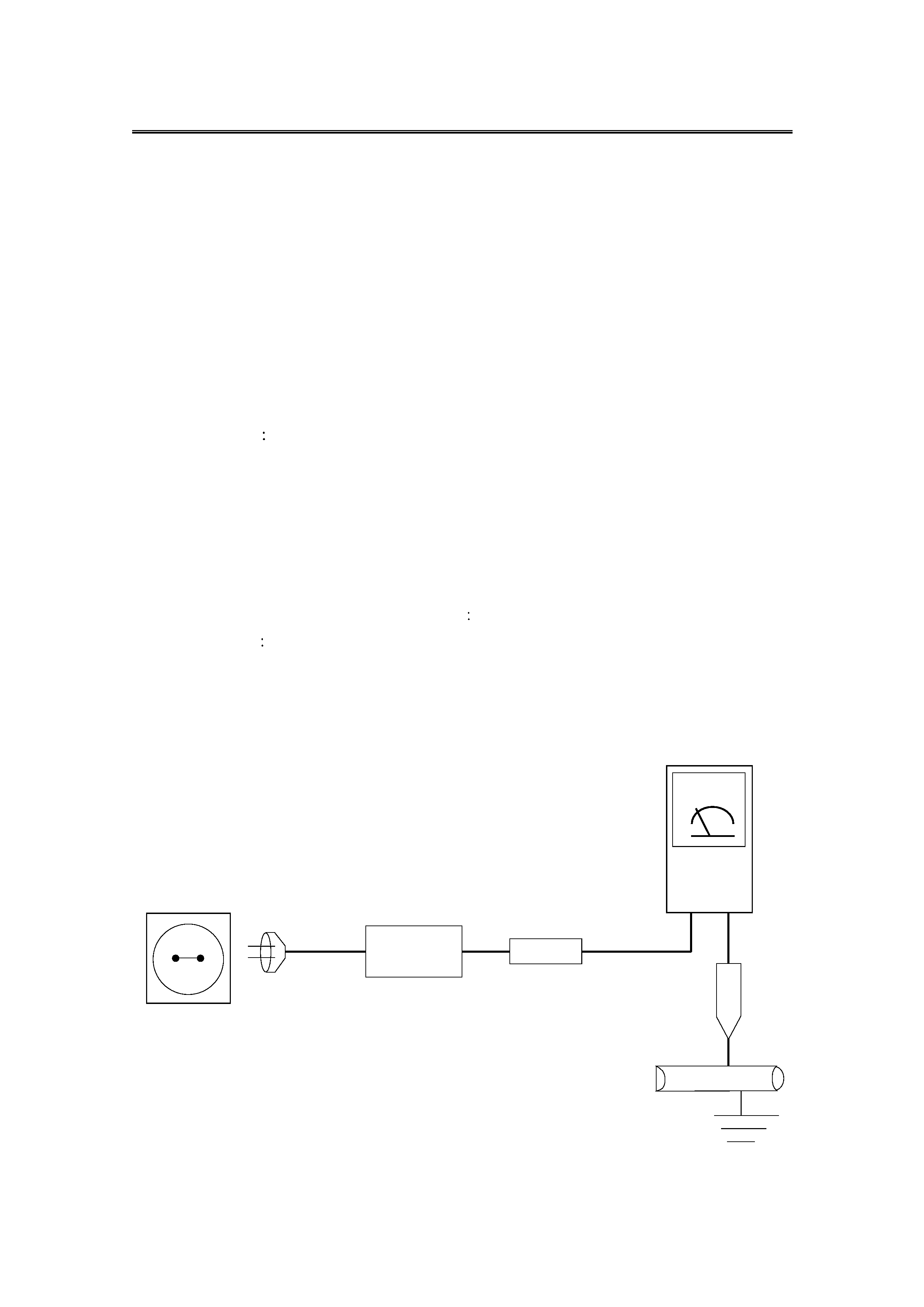
4. Leakage Current Hot Check (Figure 1-1)
Warning
Do not use an isolation transformer during this test. Use a leakage current
tester or a metering system that complies with International Electrotechnical Commission
65.(IEC 65)
ALSO TEST WITH
PLUG REVERSED
POWER
CORD
TEST ALL
EXPOSED METAL
SURFACES
EARTH
GROUND
READING SHOULD NOT
BE ABOVE
<0.7mA PEAK AC<2mA DC.
DEVICE
UNDER
TEST
LEAKAGE
CURRENT
TESTER

5. With the unit completely reassembled, plug the AC line cord directly to the power outlet.
With the unit s AC switch first in the ON position and then OFF, measure the current
between a known earth ground (metal water pipe, conduit, etc.) and all exposed metal
parts, including
handle brackets, metal cabinets, screwheads and control shafts.
The current measured should not exceed < 0.7 mA peak AC < 2mA DC.
Reverse the power-plug in the AC outlet and repeat the test.
6. X-ray Limits
The picture tube is especially designed to prohibit X-ray emissions.
To ensure continued X-ray protection, replace the picture tube only with one that is the
same type as the original. Carefully reinstall the picture tube shields and mounting
hardware
these also provide X-ray protection.
7. High Voltage Limits
High voltage must be measured each time servicing is done on the +B, horizontal
deflection or high voltage circuits.
8. High voltage is maintained within specified limits by close-tolerance, safety-related
components and adjustments. If the high voltage exceeds the specified limits, check
each of the special components.
9. Design Alteration Warning
Never alter or add to the mechanical or electrical design of this unit.
Example
Do not add auxiliary audio or video connectors. Such alterations might
create a safety hazard. Also, any design changes or additions will void the
manufacturer s warranty.
10. Components, parts and wiring that appear to have overheated or that are otherwise
damaged should be replaced with parts that meet the original specifications. Always
determine the cause of damage or overheating, and correct any potential hazards.
11. Observe the original lead dress, especially near the following areas
Antenna wiring, sharp edges, and especially the AC and high voltage power supplies.
Always inspect for pinched, out-of-place, or frayed wiring.
Do not change the spacing between components and the printed circuit board. Check
the AC power cord for damage. Make sure that leads and components do not touch
thermally hot parts.
12. Picture Tube Implosion Warning
The picture tube in this receiver employs "integral implosion" protection.
To ensure continued implosion protection, make sure that the replacement picture tube
is the same as the original.
13. Do not remove, install or handle the picture tube without first putting on shatterproof
goggles equipped with side shields.
Never handle the picture tube by its neck. Some "in-line" picture tubes are equipped
with permanetly attached diflection yoke
do not try to remove such "permanently
attached" yokes from the picture tube.
4

5
14. Product Safety Notice
Some electrical and mechanical parts have special safety-related characteristics which
might not be obvious from visual inspection.
These safety features and the protection they give might be lost if the replacement
component differs from the original-even if the replacement is rated for higher voltage,
wattage, etc.
Components that are critical for safety are indicated in the circuit diagram by
shading(
)
Use replacement components that have the same ratings, especially for flame
resistance and dielectric strength specifications. A replacement part that does not have
the same safety characteristics as the original might create shock, fire or other hazards.
1-2. Servicing Precautions
Waning 1
First read the "Safety Precaution" section of the manual.
If some unforeseen circumstance creates a conflict between the servicing and
safety precautions, always follow the safety precaution.
Warning 2
An electrolytic capacitor installed with the wrong polarity might explode.
1. Servicing Precautions are printed on the cabinet. Follow them.
2. Always unplug the unit s AC power cord from the AC power source before attempting
to
(a) Remove or reinstall any component or assembly, (b) Disconnect an electrical
plug or connector, (c) Connect a test component in parallel with an electrolytic capacitor.
3. Some components are raised above the printed circuit board for safety.
An insulation tube or tape is sometimes used. The internal wiring is sometimes clamped
to prevent contact with thermally hot components.
Reinstall all such elements to their original position.
4. After servicing, always check that the screws, components and wiring have been
correctly reinstalled. Make sure that the portion around the serviced part has not been
damaged.
5. Check the insulation between the blades of the AC plug and accessible conductive parts
(examples
metal panels,. input terminals).
6. Insulation Checking Procedure
Disconnect the power cord from the AC source and
turn the power switch ON. Connect an insulation resistance meter (500V) to the blades of
the AC plug.
The insulation resistance between each blade of the AC plug and accessible conductive
parts (see above) should be greater than 1 megohm.
7. Never defeat any of the B+ voltage interlocks. Do not apply AC power to the unit (or any
of its assemblies) unless all solid-state heat sinks are correctly installed.
5