CAUTION:
Before servicing this chassis, it is important that the service technician read the "Safety
Precautions" and "Product Safety Notices" in this service manual.
ATTENTION:
Avant d'effectuer l'entretien du châassis, le technicien doit lire les «Précautions de sécurité»
et les «Notices de sécurité du produit» présentés dans le présent manuel.
VORSICHT:
Vor Öffnen des Gehäuses hat der Service-Ingenieur die ,,Sicherheitshinweise" und ,,Hinweise
zur Produktsicherheit" in diesem Wartungshandbuch zu lesen.
SERVICE MANUAL
MANUEL D'ENTRETIEN
WARTUNGSHANDBUCH
Data
contained
within
this
Service
manual is subject to alteration for
improvement.
Les données fournies dans le présent
manuel d'entretien peuvent faire l'objet
de modifications en vue de perfectionner
le produit.
Die
in
diesem
Wartungshandbuch
enthaltenen Spezifikationen können sich
zwecks Verbesserungen ändern.
SPECIFICATIONS AND PARTS ARE SUBJECT TO CHANGE FOR IMPROVEMENT
Colour Monitor
November 2002
No. 0535
CML152XW2

1
Table of Contents
1. 1. ELECTRICAL REQUIREMENTS.................................................................................2
A. LCD Panel Specification ........................................................................................................................... 2
B. CONTROLS .............................................................................................................................................. 3
C. Power Management.................................................................................................................................. 3
D. Display Modes FOR Inspections .............................................................................................................. 5
2. ADJUSTMENT CONDITIONS .........................................................................................6
A. Measuring Apparatuses Used .................................................................................................................. 6
B. Input Signal ............................................................................................................................................... 6
C. Indication................................................................................................................................................... 6
3. ADJUSTMENT OF POWER SUPPLY
.......................................................................6
4. ADJUSTMENT OF BOARDS ..........................................................................................7
A. Connection Method................................................................................................................................... 7
5. DISPLAY CONTROL BOARD.........................................................................................8
A. Description ................................................................................................................................................ 9
B. Features.................................................................................................................................................... 9
C. Block Diagram (Control CKT) ................................................................................................................... 9
D. Connector Locations............................................................................................................................... 11
E. Connector Type ...................................................................................................................................... 11
F. Connector pin assignment ...................................................................................................................... 12
6. VK-546 CONTROL PANEL BOARD .............................................................................16
A. Description .............................................................................................................................................. 16
B. Connector and Switch Locations ............................................................................................................ 16
C. Connector type........................................................................................................................................ 16
D. Connector pin Assignment...................................................................................................................... 17
7. POWER BOARD............................................................................................................19
A. Description .............................................................................................................................................. 19
B. Electrical characteristics ......................................................................................................................... 19
C. Connector locations ................................................................................................................................ 20
8. CIRCUIT DESCRIPTION ...............................................................................................21
A. Micro-Controller Circuit ........................................................................................................................... 21
B. Circuit of Plug and Play........................................................................................................................... 21
C. System Clock .......................................................................................................................................... 21
D. Image Engine (Zoom) ............................................................................................................................. 21
E. Power Regulator ..................................................................................................................................... 21
9. INTRODUCTION............................................................................................................22
A. Front Panel Control and Led................................................................................................................... 22
B. Rear Panel connector Input Signals......................................................................................................... 24
10. TROUBLESHOOTING .............................................................................................25
A. Main Procedure....................................................................................................................................... 25
11. MECHANICAL PARTS AND DRAWINGS ...............................................................30
12. PCB PARTS AND DRAWINGS................................................................................40
2
1. 1. ELECTRICAL REQUIREMENTS
A. LCD Panel Specification
Display:
15 inch (15" viewable image size): active matrix: thin film transistor
(TFT): liquid crystal display (LCD): 0.297 mm dot pitch: R.G.B.
Vertical stripe 200 cd//m
2 white luminance, typical: 300:1 contrast
ratio, typical
Compatibility:
640 x 350: VGA-350
720 x 400: VGA text
640 x 400: VGA-GRAPH
640 x 480: VGA, 60Hz to 75 Hz vertical refresh rate
800 x 600: 56Hz to 75 Hz vertical refresh rate
1024 x 768 non-interlaced: 60Hz to 75 Hz vertical refresh rate
Synchronization
Frequencies:
Horizontal:
24 kHz to 60 kHz
Vertical:
56 Hz to 75 Hz (1024 x 768 is up to 75 Hz)
Pixel Frequency: 21 Mhz to 78 Mhz
Resolution:
Horizontal:
1024 dots
Vertical:
768 lines
Active Display Area:
Horizontal:
304.1 mm
Vertical:
228.1 mm
Viewing Angles:
AU
Up 40deg down 60deg (TYP)
Left 60deg, Right 60deg (TYP)
CR > 10
Hannstar
Up 45deg down 55deg (TYP)
Left 65deg, Right 65deg (TYP)
CR > 10
Display Colors:
6-bits driver
Power Supply:
AC 100 to 240V worldwide input, 50 / 60Hz
Power Consumption:
Typical: 25W on mode +10 / -25%
Environmental:
Operating temperature: 0ºC to 50ºC
Storage temperature: -20ºC to 60ºC
Storage humidity: 10%~90%
3
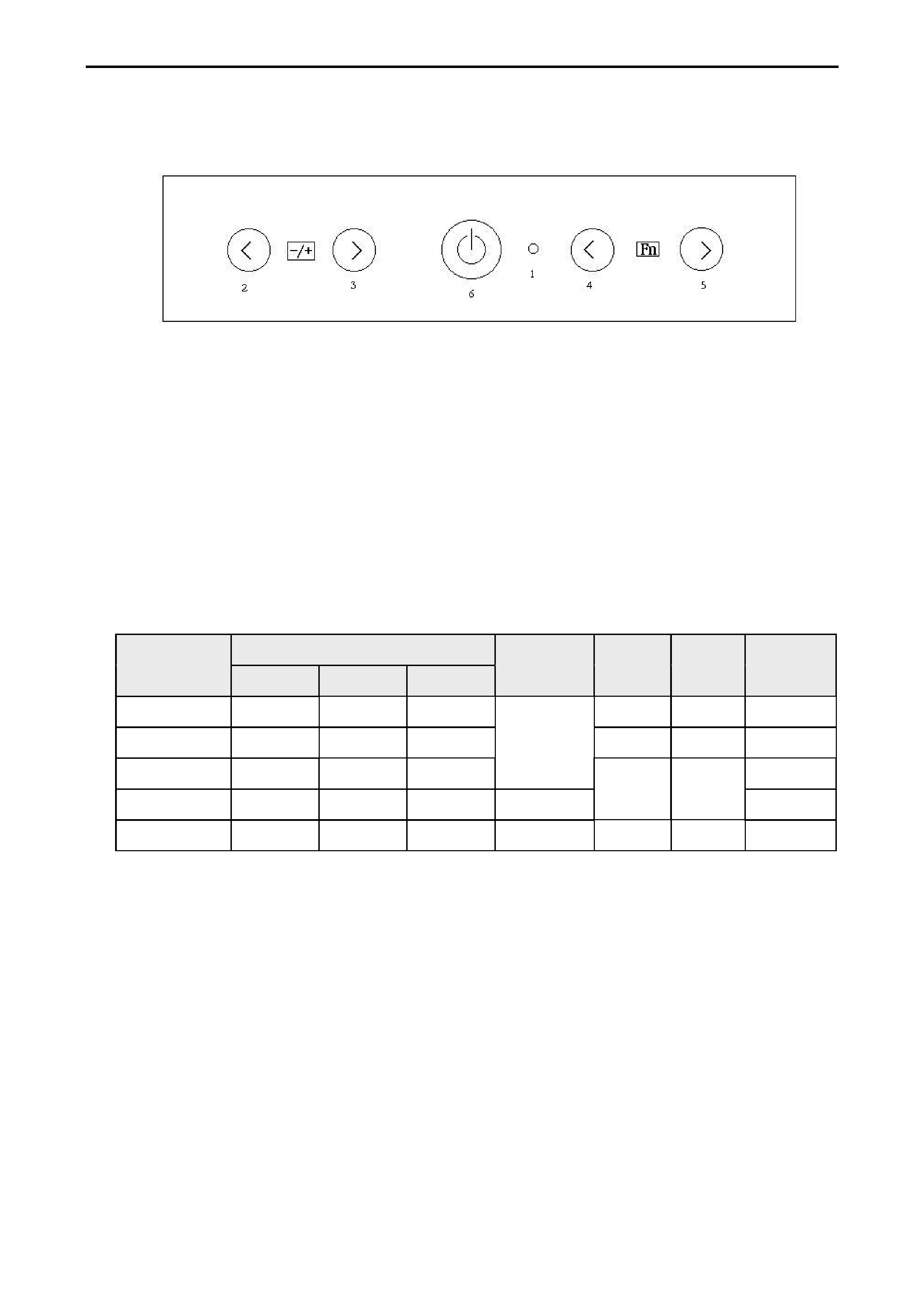
B. CONTROLS
B-1 Control panel (monitor front panel)
1. Power LED, ( Please refer to C-2 LED definition table)
2. Adjust decrease.
3. Adjust increase
4. Function select counter-clockwise.
5. Function select clockwise.
6. Power ON/OFF switch, push to ON and push to OFF. (toggle switch)
C. Power Management
C-1 Power Management condition and status
State
Signals
Power
Video
LCD
LED
Horizontal
Vertical
Video
Supply
Circuit
On
Pulses
Pulses
Active
On
On
On
Green
Stand-by
No Pulses
Pulses
Blanking
Off
Off
Yellow
Suspend
Pulses
No Pulses
Off
No pulses
No pulses
Blacking
On
Yellow
DC Power off
Don't care
Don't care
Don't care
Off
Off
Off
Off
4
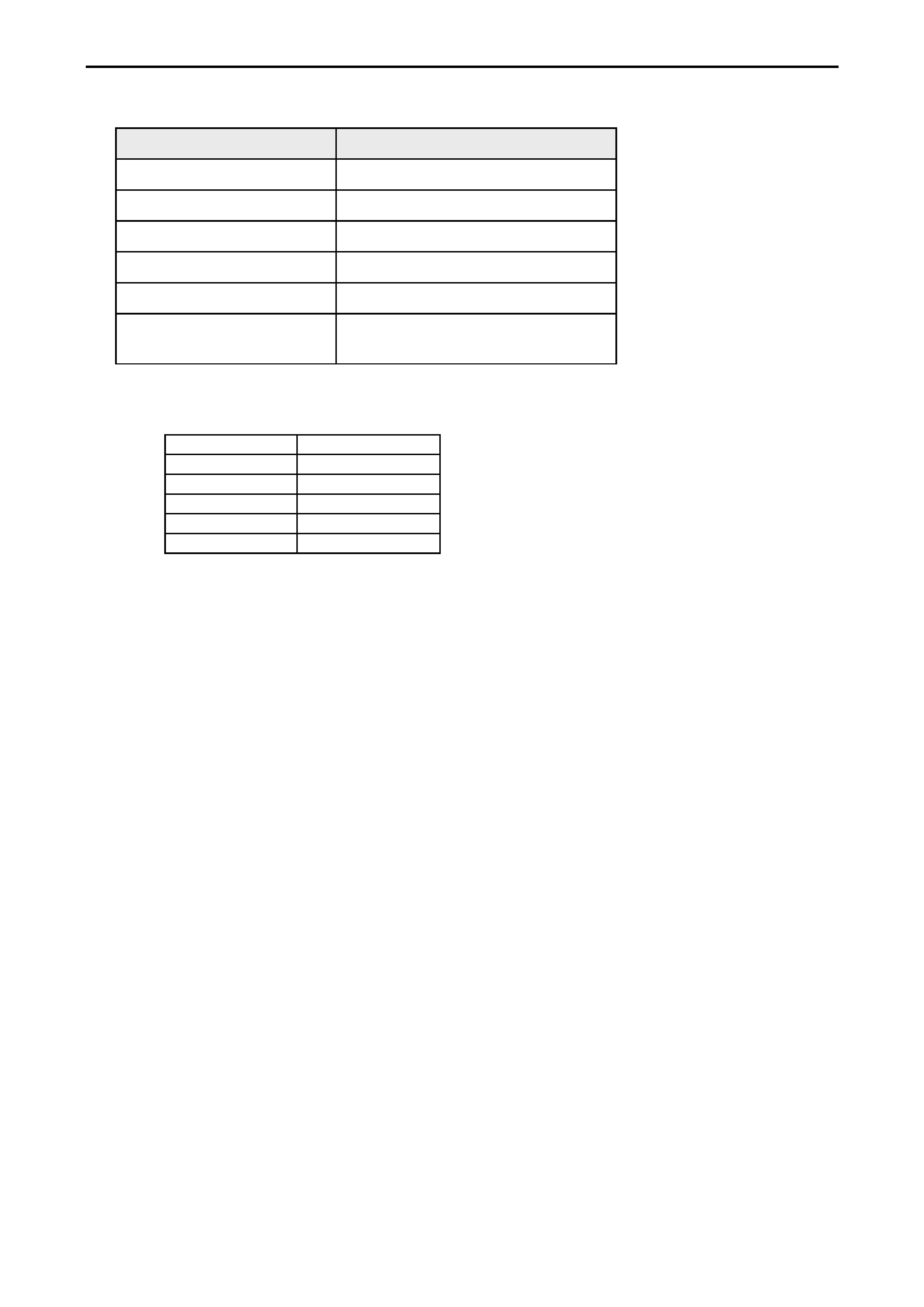
C-2 LED definition Table
State
LED
On mode
Green
Stand-by
Yellow
Suspend
Yellow
Off mode
Yellow
power off
Dark
disconnection
1. Yellow(stand-by; suspend; off mode)
2. LED Dark (power off)
C-3 Power Consumption
Meet VESA DPMS Proposal
On mode
25 Wmax
Stand-by
5 Wmax
Suspend
5 Wmax
Off mode
5 Wmax
DC power off
5 Wmax
disconnection
5 Wmax
Measured from AC input, and not include audio at power-saving state
The stand-by, suspend and off mode recover to on mode about 3 seconds.