APRIL 2004
HHEA-MANUFACTURING DIVISION
PA
No. 0186
51S715
DP47
57S715
DP47
R/C: CLU-3842WL
N
N T
T S
S C
C
D
DP
P4
47
7
C
Ch
ha
as
ss
siis
s
SERVICE MANUAL
CONTENTS
IMPORTANT SAFETY INSTRUCTIONS .............................................................................. 2
SERVICING PRECAUTIONS .............................................................................................. 6
TECHNICAL CAUTIONS .................................................................................................... 11
SPECIFICATIONS .............................................................................................................. 13
GENERAL INFORMATION ..................................................................................................14
CUSTOMIZED PICTURE AND SOUND ADJUSTMENTS ..................................................19
DISPLAY PICTURE FORMATS ..........................................................................................29
SERVICE ADJUSTMENTS..................................................................................................31
PROTECTION CIRCUIT BLOCK DIAGRAM ......................................................................83
TROUBLESHOOTING FLOW CHART ................................................................................84
DC VOLTAGE TABLES........................................................................................................90
WAVEFORMS....................................................................................................................104
CIRCUIT SCHEMATIC DIAGRAM ....................................................................................114
PRINTED CIRCUIT BOARDS ..........................................................................................129
BLOCK DIAGRAM ............................................................................................................148
WIRING DIAGRAM............................................................................................................149
CHASSIS WIRING DIAGRAM ..........................................................................................150
EXPLODED VIEW ............................................................................................................152
EXPLODED VIEW PARTS LIST........................................................................................154
REPLACEMENT PARTS LIST ..........................................................................................156
QUICK REFERENCE PARTS LIST (IC & UNIT) ..............................................................179
DISASSEMBLY INSTRUCTIONS......................................................................................182
CAUTION:
These servicing instructions are for use by qualified service personnel only. To reduce the risk of
electric shock do not perform any servicing other than that contained in the operating instructions
unless you are qualified to do so.
Before servicing this chassis, it is important that the service
technician read the "IMPORTANT SAFETY INSTRUCTIONS" in this service manual.
SAFETY NOTICE
USE ISOLATION TRANSFORMER WHEN SERVICING
Components having special safety characteristics are identified by a
on the schematics and on the parts list in this
Service Data and its supplements and bulletins. Before servicing the chassis, it is important that the service technician
read and follow the "Important Safety Instructions" in this Service Manual.
PROJECTION COLOR TELEVISION
SPECIFICATIONS AND PARTS ARE SUBJECT TO CHANGE FOR IMPROVEMENT
!
TO GO TO A CHAPTER, CLICK ON ITS HEADING BELOW
PWB PARTS LIST..............................................................................................................183 Updated 3/18/05
Version 0186.4
updated 10/06/05
updated 02/13/07
2
DP47
Components having special safety characteristics are identified by a
on the schematics and on the parts list in this service manual
and its supplements and bulletins. Before servicing this chassis, it is important that the service technician read and follow the
"Important Safety Instructions" in this Service Manual.
For continued X-Radiation protection, replace picture tube with original type or Hitachi approved equivalent type.
This Service Manual is intended for qualified service technicians; it is not meant for the casual do-it-yourselfer.
Qualified
technicians have the necessary test equipment and tools, and have been trained to properly and safely repair complex products
such as those covered by this manual.
Improperly performed repairs can adversely affect the safety and reliability of the product and may void warranty. If you are not
qualified to perform the repair of this product properly and safely, you should not risk trying to do so and refer the repair to a
qualified service technician.
WARNING
Lead in solder used in this product is listed by the California Health and Welfare agency as a known reproductive toxicant which may
cause birth defects or other reproductive harm (California Health and Safety Code, Section 25249.5).
When servicing or handling circuit boards and other components which contain lead in solder, avoid unprotected skin contact with solder.
Also, when soldering do not inhale any smoke or fumes produced.
This television receiver provides display of television closed captioning in accordance with section 15.119 of the FCC rules.
Do not place any objects on the top of the television which may fall or cause a child to climb to retrieve the objects.
Projection TV's are heavy and can mark or damage floor surfaces (especially wood flooring) if moved improperly. Do not slide or
force TV into position. Always roll TV allowing casters at bottom of unit to help steep and position the TV.
PREVENTION OF SCREEN BURN
This wide screen TV is designed to display wide screen pictures. Images hould be viewed mostly in wide screen format or zoomed to
fit the screen with moving pictures. Use of side panels, top and bottom panels of standard picture formats should only be 15% of your
total viewing time to prevent uneven aging of the phosphors. Phosphors in the lighted area of the picture will age more rapidly than
the gray areas. Continuous on-screen displays such as video games, stock market quotations, computer generated grphics, and
other fixed (non-moving) patters can cause permanent damage to television receivers. Such "SCREEN BURNS" constitute misuse
and are NOT COVERED by your HITACHI Factory Warranty.
PUBLIC VIEWING OF COPYRIGHTED MATERIAL
Pulic viewing of programs broadcast by TV stations and cable companies, as well as prgrams from other sources, may require prior
authorization from the broadcaster or owner of the video program material.
This product incorporates copyright protection technology that is protected by U.S. patents and other intellectual property rights. Use
of this copyright protection technology must be authorized by Macrovision Corporation, and is intended for home and other limited
consumer uses only unless otherwise authorized by Mcrovision. Reverse engineering or disassembly is prohibited.
FEDERAL COMMUNICATIONS COMMISSION NOTICE
This equipment has been tested and found to comply with the limits for a Class B digital device, pursuant to Part 15 of the FCC
Rules. These limits are designed to provide reasonable protection against harmful interference in a residential installation. This
equipment generates, uses, and can radiate radio frequency energy and, if not installed and used in accordance with the instructions,
may cause harmful interference to radio communications. However, there is no guarantee that interference will not occur in a
particular installation. If this equipment does cause harmful interference to radio or television reception, which can be determined by
turning the equipment off and on, the user is encouraged to try to correct the interference by one or more of the following measures:
· Reorient or relocate the receiving antenna.
· Increase the separation between the equipment and the receiver.
· Connect the equipment into an outlet on a circuit different from that to which the receiver is connected.
· Consult the dealer or an experienced radio/television technician for help.
This digital television is capable of receiving analog basic, digital basic and digital premium cable television programming by direct
connection to a cable system providing such programming. A CableCARD provided by your cable operator is required to view
encrypted digital programing. Certain advanced and interactive digital cable services such as video-on-demand, a cable operator's
enhanced program guide and data-enhanced television services may require the use of a set-top-box. For more information call your
local cable company.
IMPORTANT SAFETY INSTRUCTIONS
USE ISOLATION TRANSFORMER WHEN SERVICING
!
TABLE OF CONTENTS
This product contains lead. Dispose of this product in accordance with applicable environmental laws. For
product recycling and disposal information, contact you local government agency or the Electronic Industries
Alliance at www.eiae.org (in the US) or the Electronic Product Stewardship Canada at www.epsc.ca (in Canada).
For more information, call "1-800-HITACHI.
3
DP47
IMPORTANT SAFETY INSTRUCTION
1. Before returning an instrument to the customer, always
make a safety check of the entire instrument, including
but not limited to the following items.
a. Be sure that no built-in protective devices are
defective and/or have been deleted during servicing.
(1) Protective shields are provided on this chassis to
protect both the technician and the customer.
Correctly replace all missing protective shields,
including any removed for servicing convenience. (2)
When reinstalling the chassis and/or other assembly
in the cabinet, be sure to put back in place all
protective devices, including but not limited to,
nonmetallic control knobs, insulating fishpaper,
adjustment and compartment covers/shields, and
isolation resistor/capacitor networks.
Do not operate
this instrument or permit it to be operated without
all protective devices correctly installed and
functioning. Servicers who defeat safety features
or fail to perform safety checks may be liable for
any resulting damage.
b. Be sure that there are no cabinet openings through
which an adult or child might be able to insert their
fingers and contact a hazardous voltage. Such
openings include, but are not limited to (1) spacing
between the picture tube and cabinet mask, (2)
excessively wide cabinet ventilation slots, and (3) an
improperly fitted and/or incorrectly secured cabinet
back cover.
c.
Antenna Cold Check With the instrument AC plug
removed from any AC source, connect an electrical
jumper across the two AC plug prongs. Place the
instrument AC switch in the on position. Connect one
lead of an ohmmeter to the AC plug prongs tied
together and touch the other ohmmeter lead in turn to
each tuner antenna input, exposed terminal screw
and, if applicable, to the coaxial connector. If the
measured resistance is less than 1.0 megohms or
greater than 5.2 megohms, an abnormality exists that
must be corrected before the instrument is returned to
the customer. Repeat this test with the instrument AC
switch in the off position.
d.
Leakage Current Hot Check With the instrument
completely reassembled, plug the AC line cord
directly into a 120V AC outlet. (Do not use an isolation
transformer during this test.) Use a leakage current
tester or a metering system that complies with
American National Standards Institute (ANSI) C101.0
Leakage Current for Appliances and Underwriters
Laboratories (UL) 6500, (9.1.1). With the instrument
AC switch first in the on position and then in the off
position, measure from a known earth ground (metal
waterpipe, conduit, etc.) to all exposed metal parts of
the instrument (antennas, handle bracket, metal
cabinet, screw heads, metallic overlays, control
shafts, etc.), especially any exposed metal parts that
offer an electrical return path to the chassis. Any
current measured must not exceed 0.5 MIU. Reverse
the instrument power cord plug in the outlet and
repeat test.
ANY MEASUREMENTS NOT WITHIN THE LIMITS
SPECIFIED HEREIN INDICATE A POTENTIAL
SHOCK HAZARD THAT MUST BE ELIMINATED
BEFORE RETURNING THE INSTRUMENT TO THE
CUSTOMER OR BEFORE CONNECTING THE
ANTENNA OR ACCESSORIES.
e.
High Voltage This receiver is provided with a hold
down circuit for clearly indicating that voltage has
increased in excess of a predetermined value.
Comply will all notes described in this Service Manual
regarding this hold down circuit when servicing, so
that this hold down circuit may correctly be operated.
f.
Service Warning With maximum contrast, operating
high voltage in this receiver is lower than
32.0 kV. In
case any component having influence on high voltage
is replaced, confirm that the high voltage with
maximum contrast is lower than
32.0 kV.
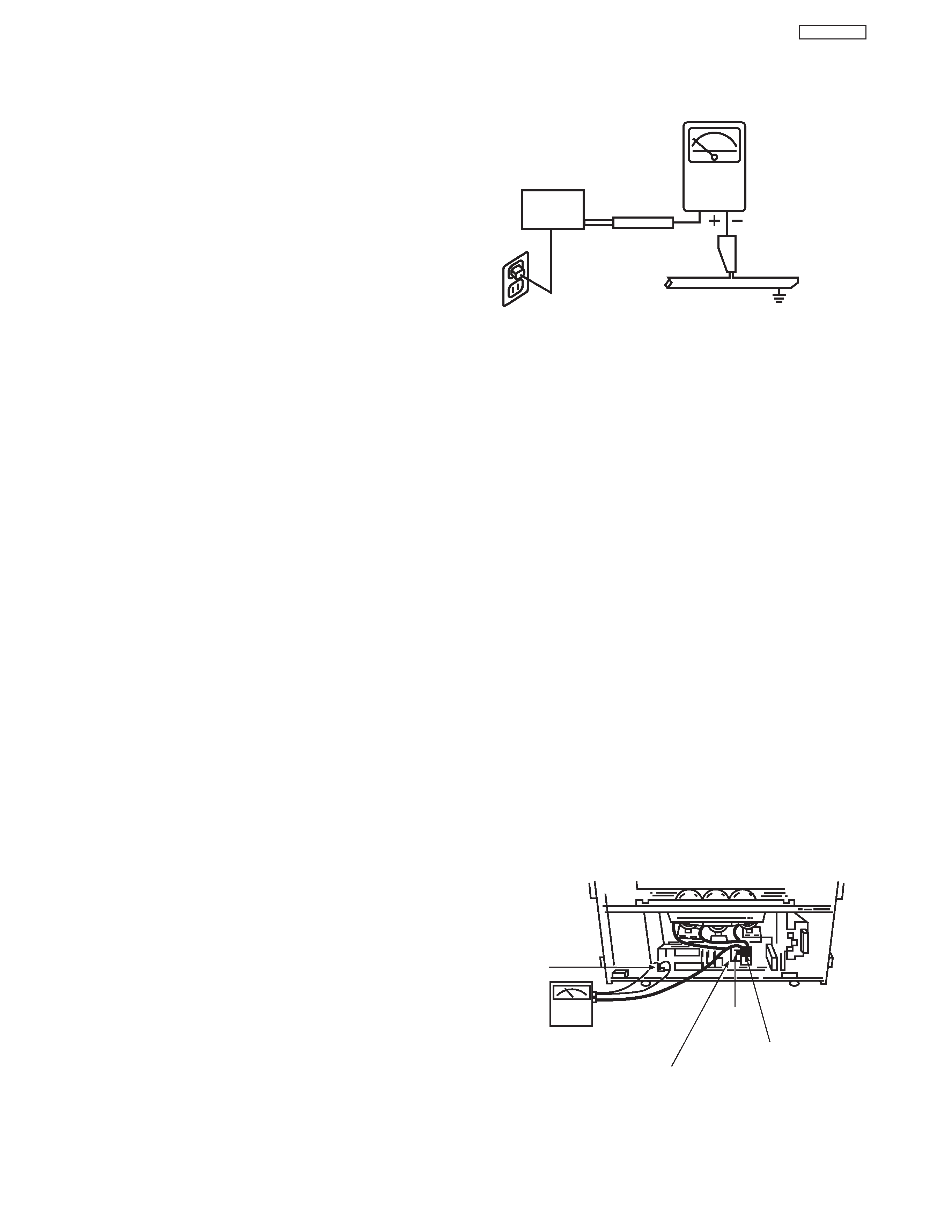
To measure H.V. use a high impedance H.V. meter.
Connect (-) to chassis earth and (+) to the CRT anode
button. (See the following connection diagram.)
Note: Turn power switch off without fail before the
connection to the anode button is made.
LEAKAGE
CURRENT
TESTER
(READING
SHOULD NOT
BE ABOVE 0.5MIU)
EARTH
GROUND
TEST ALL
EXPOSED
METAL SURFACES
DEVICE
UNDER
TEST
2-WIRE CORD
ALSO TEST WITH PLUG
REVERSED
(USING AC ADAPTER
PLUS AS REQUIRED)
Chassis
ground
High Impedance
H.V. meter
Deflection P.W.B.
FBT
(TH02)
High voltage
connector
AC Leakage Test
4
DP47
g.
X-radiation TUBE: The primary source of X-
radiation in this receiver is the picture tube. The tube
utilized for the above mentioned function in this
chassis is specially constructed to limit X-radiation
emissions.
For continued X-radiation protection, the replacement
tube must be the same type as the original, Hitachi
approved type.
When troubleshooting and making test measure-
ments in a receiver with a problem of excessive high
voltage, avoid being unnecessarily close to the pic-
ture tube and the high voltage component.
Do not operate the chassis longer than is necessary
to locate the cause of excessive voltage.
h.
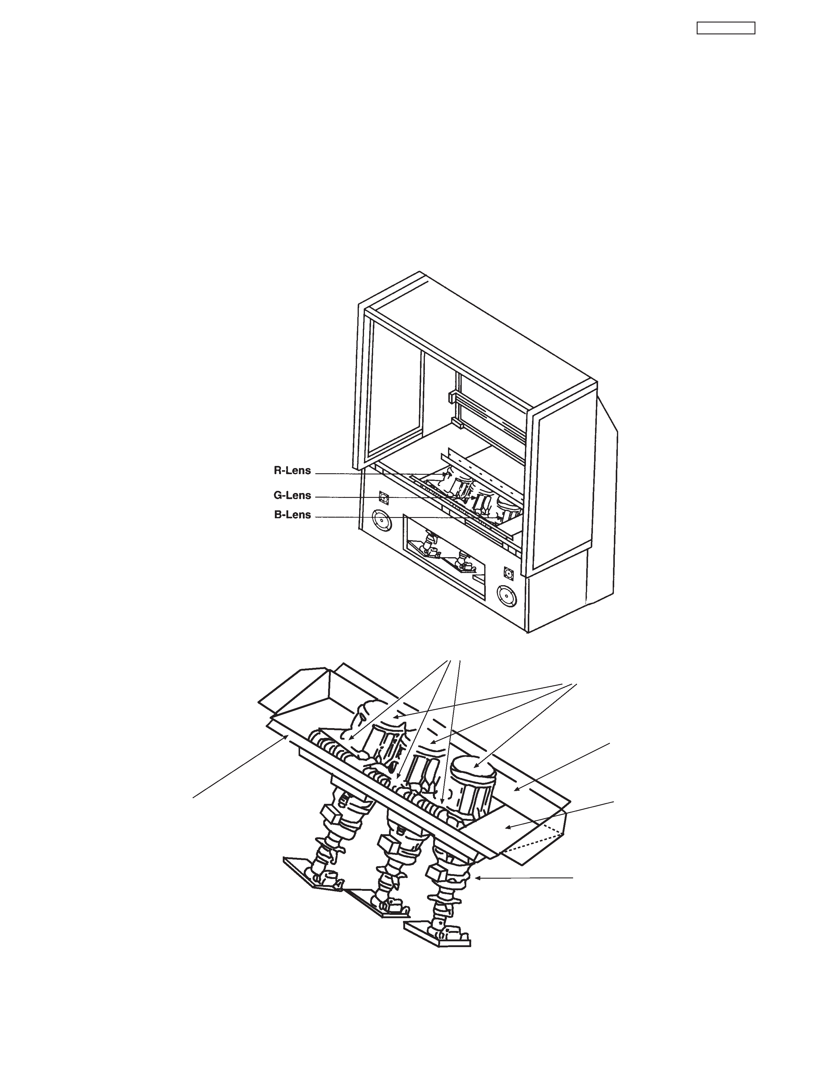
X-radiation Shield
1. This receiver is provided with X-ray shield plates
for protection against X-radiation. Do not remove
X-ray shield plates A, B, or C shown in Fig. 1
unnecessarily,
when
troubleshooting
and/or
making test measurements.
2. To prevent X-radiation, after replacement of
picture tube and lens, confirm these components
to be fixed correctly to bracket and cabinet, and
not to be taken off easily.
Shield Plate A
Glass Lens for Shielding
Shield Plate B
Shield Plate C
Shield Plate D
Detailing X-radiation shield
Shield Plate C
Fig. 1. Installation of shield lens, shield cover and shield plates (oblique view).
IMPORTANT SAFETY INSTRUCTIONS