1
No.
HITACHI
SERVICE MANUAL
42HDM12
Be sure to read this manual before servicing. To ensure safety from fire, electric shock, injury, harmful
radiation and materials, various measures are provided in this Plasma Monitor.
Be sure to read cautionary items described in the manual before servicing.
These servicing instructions are for use by qualified service personnel only. To reduce the risk of electric
shock, do not perform any servicing other than that described in the operating instructions unless you are
qualified to do so.
1. Since the Panel Module and the front Filter are made of glass, handling the broken Module and Filter
carefully and with caution in order not to receive injury.
2. Replacement work should be started after the Panel Module and the AC/DC Power supply have
become sufficiently cool.
3. Special care should be taken when working near the display area in order not to damage its surface.
4. The Panel Module should not be touched with bare hands in order to protect its surface from
blemishes and damage.
5. It is recommended that you use clean soft gloves during the replacement work in order to protect not
only the display area of the Panel Module but also yourself.
1. Features -------------------------------------------3
2. Specifications ------------------------------------4
3. Component Names -----------------------------5
4. Service points ------------------------------------7
5. Adjustment ----------------------------------------8
6. Troubleshooting --------------------------------11
7. Block diagram ---------------------------------- 22
8. Connection diagram ---------------------------- 24
9. Wiring diagram ----------------------------------- 25
10. Basic block diagram --------------------------- 26
11. Printed wiring board diagram ---------------- 27
12. Disassembly diagram ------------------------- 34
13. Replacement parts list ------------------------ 36
SPECIFICATIONS AND PARTS ARE SUBJECT TO CHANGE FOR IMPROVEMENT.
Plasma Monitor
Caution
Contents
Service Warning
TA 002
Updated 3/24/06
Ver TA 002.3
Updated 1/3/07
Updated 1/10/07
2
CAUTION FOR SAFETY
Please read this page before repair the monitor.
The following safety precautions are designed to help you stay safe and prevent accidents during the repair
work.
Please take note of these cautionary flags.
Warning
This means "Potential to sustain injury or even death."
Caution
This means "Potential to sustain breakage or irreparable damage."
Also note these cautionary icons
This means "CAUTION"
This means "MUST"
This means "POTENTIAL ELECTRIC
SHOCK"
This means "DO NOT"
WARNING
Follow instructions.
Must use same types of wires and components.
The cabinet, chassis, and labels are parts
that require attention. You must follow the
caution notes and safety instructions
presented throughout this User Manual to
prevent damage to them or injury to
yourself.
Prevent electric shock.
The Monitor uses special tubes and tapes
made from insulated materials. Moreover,
some materials are kept from making
contact with the PWB for the sake of
safety.Internal leads are kept from hot
parts or high voltage parts by means of
clamps or other measures. As such, you
must restored these parts to their original
conditions in order to prevent electric
shock or fire.
Perform safety check when done.
Exercise caution while working on the
device as the Monitor contains high
voltage parts and power supply.It is
possible to sustain severe injury or death
if you accidentally touch the wrong
parts.You must disconnect the power
supply while servicing, reassembling, or
change parts. If you touch a live
connection it is possible to sustain severe
injury or death.
Use recommended components.
Every part (such as removed screws,
components, and wiring) must be
restored to their prior conditions after
servicing.Be sure to check everything
that was repaired for damage or
mistakes. Also measure the insulated
impedance with a meg-ohm meter to
confirm that the impedance value is more
than 4M ohm.If the impedance value is
less than 4M ohm, then electric shock or
fire may result.
Do not try to check the HDCP code and
combination circuit.
Use only the recommended components
or componentst that structurally identical
to the originals. This is to ensure safety
and reliability. Pay special attention to
parts in the parts list and circuit diagrams
marked with
. If you use
non-recommended components, then
electric shock or fire may result.
Never remove the shield case protecting
the HDCP code and combination circuit.

3
PRECAUTIONS
Cleaning the monitor's plasma screen panel
Before cleaning the monitor, turn it off and disconnect the power plug from the power outlet. To prevent
scratching or damaging of the plasma screen face, do not knock or rub the surface with sharp or hard objects.
Clean the screen with a soft cloth moistened with warm water and dry with a second soft cloth. If it is not
enough, then use a cloth with mild detergent. Do not use harsh or abrasive cleaners.
Cleaning the monitor's cabinet
Use a soft cloth to clean the monitor's cabinet and control panel. When excessively soiled, dilute a neutral
detergent in water, wet and wring out the soft cloth in it, gently clean the cabinet, and then wipe it down with a
dry soft cloth.
Never use acid/alkaline detergents, alcoholic detergents, abrasive cleaners, powder soaps, OA cleaners, car
wax, glass cleaners, and so on. They will cause discoloration, scratches or cracks.
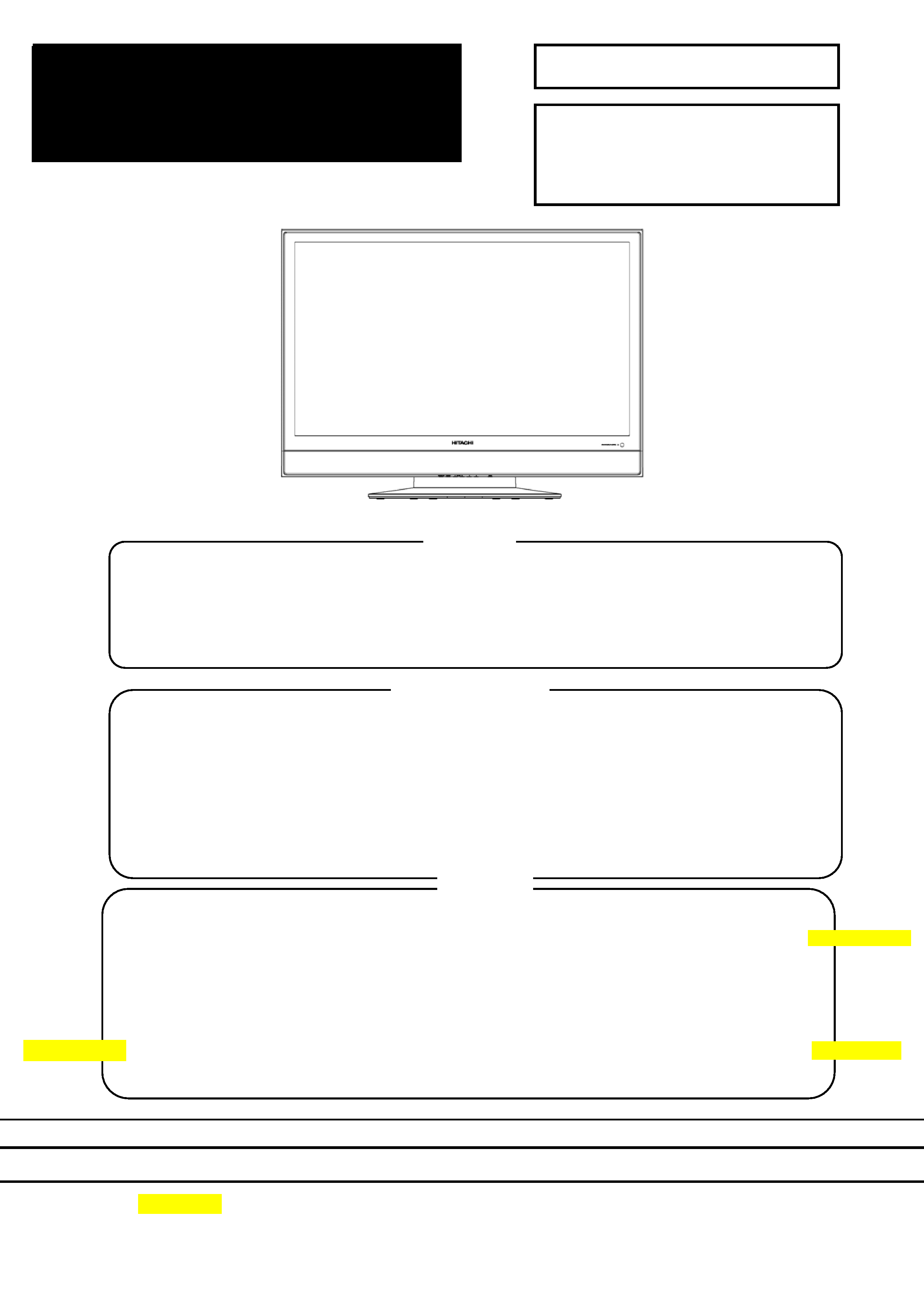
1. Features
High definition Plasma display panel
The 42-inch color plasma display panel, with a resolution of 1024 (H) x 1024(V) pixels, creates a widescreen
picture. This panel features a thin form factor and can be hung on a wall with an optional wall mounting kit.
High Performance Digital Processor
This panel displays a wide range of personal computer signals from 640 x 400 VESA, 640 x 480 VGA to 1024
x 768, 1280 x 1024 XGA.(RGB Analog input).
Easy-to-use remote control and on-screen display system
The included remote control operates all Monitor functions. Futhermore, the on-screen display system shows
the status of the control settings in an easy-to-view fashion.
Power saving system
When connected to a VESA DPMS-compliant PC, the monitor cuts its power consumption while idle.
4
2. Specifications
Display
dimensions
Approx. 42inches (922 (H) x 522 (V) mm, diagonal 1059mm)
Panel
Resolution
1024 (H) x 1024 (V) pixels
Net dimensions
1036 (W) x 775 (H) x 330 (D) mm (With stand) 1036 (W) x 713 (H) x 93 (D) mm (Without stand)
Net weight
42.5 kg (With stand) 35 kg (Without stand)
Temperatur
Operating: 0°C to 40°C, Storage: -15°C to 60°C
Ambient
conditions
Relative umidity
Operating: 20% to 80%, Storage: 20% to 90% (non-condensing)
Power supply
AC100 - 240V, 50/60Hz
Power consumption/at standby
<350W / <1W
Audio output
Built in 10W + 10W (8 ) speakers
(RGB input)
Input terminals
ANALOG RGB input terminal (D-sub 15-pin)
ANALOG RGB/HDMI audio input terminal (3.5mm Stereo Mini Jack)
Video signals
0.7 Vp-p
Input signals
Sync signals
H/V separate, TTL level [2k ]
H/V composite, TTL level [2k ]
Recommended signal
17 modes
(Video input)
Input terminals
COMPOSITE VIDEO input terminal (RCA)
L/R COMPOSITE AUDIO input terminal (RCA)
S-VIDEO input teminal (RCA)
L/R S-VIDEO AUDIO input terminal (RCA)
Y-PB/CB PR/CR input terminal (RCA)
L/R Y-PB/CB PR/CR AUDIO input terminal (RCA)
HDMI input terminal (HDMI 19-pin)
Input signals
Video signals
Composite video: PAL, SECAM, NTSC3.58, NTSC4.43
Component - YCBCR/YPBPR video: 480i, 576i, 480p, 576p, 1080i/50, 1080i/60, 720p/50, 720p/60
S-Video: PAL, SECAM, NTSC4.43, NTSC3.58
HDMI: HDMI input signal
Output Signal
Video Output: Composite video output terminal (RCA)
Audio Output: L/R audio output terminal (RCA)/Subwoofer output terminal(RCA)
Recommended signal
19 modes
It takes at least 30 minutes to attain the maximum picture quality.
Applicable video signals for each input terminal
RCA
HDMI
D-sub
Remarks
Signal Type
Terminal
Composite Video
S-Video
Component
DVD/STB
RGB
ANALOG RGB
HDMI
COMPOSITE
S-VIDEO
Y-PB/CB PR/CR
1080i/720p/576p/576i/480p/480i
inputs.
( : Avaliable)
5
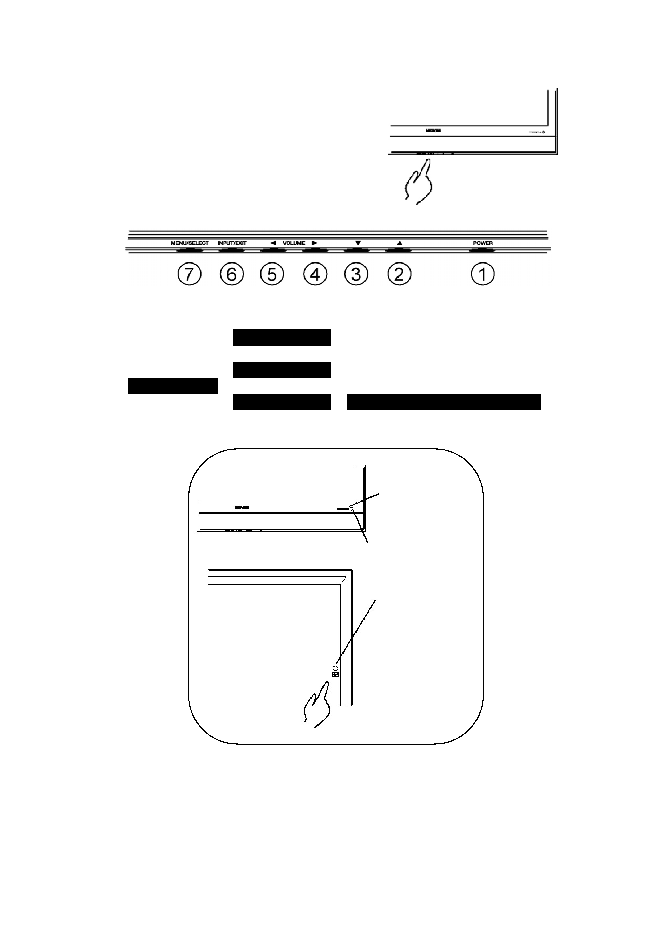
3. Component names
Main unit
Control panel
Al Adjustment buttons are located on the bottom of
the control panel
Indications for each button's function can be found
on the inside of the control panel cover.
1. POWER
5. VOL
2. UP
5. LEFT
3. DOWN
6. INPUT
4. VOL
6. EXIT
4. RIGHT
7. MENU
Normal Button Action
7. SELECT
Button Action when MENU engaged
Remote-control receiver
Power lamp
Main power switch
The main
power switch is
located at the
back, on the
right side.