CA6110D
Acoustic Amplifier
User's Guide
CA6110D Acoustic Amplifier
Table of Contents:
IMPORTANT SAFETY INSTRUCTIONS
· READ, FOLLOW, HEED, AND KEEP ALL INSTRUCTIONS AND WARNINGS.
· DO NOT OPERATE NEAR ANY HEAT SOURCE AND DO NOT BLOCK ANY VENTILATION OPENINGS ON THIS APPARATUS. FOR PROPER OPERATION, THIS UNIT REQUIRES 3"
(75CM) OF WELL VENTILATED SPACE AROUND HEATSINKS AND OTHER AIR FLOW PROVISIONS IN THE CABINET.
· DO NOT USE THIS APPARATUS NEAR SPLASHING, FALLING, SPRAYING, OR STANDING LIQUIDS.
· CLEAN ONLY WITH LINT-FREE DAMP CLOTH AND DO NOT USE CLEANING AGENTS.
· ONLY CONNECT POWER CORD TO A POLARIZED, SAFETY GROUNDED OUTLET WIRED TO CURRENT ELECTRICAL CODES AND COMPATIBLE WITH VOLTAGE, POWER, AND
FREQUENCY REQUIREMENTS STATED ON THE REAR PANEL OF THE APPARATUS.
· PROTECT THE POWER CORD FROM DAMAGE DUE TO BEING WALKED ON, PINCHED, OR STRAINED.
· UNPLUG THE APPARATUS DURING LIGHTNING STORMS OR WHEN UNUSED FOR LONG PERIODS OF TIME.
· ONLY USE ATTACHMENTS, ACCESSORIES, STANDS, OR BRACKETS SPECIFIED BY THE MANUFACTURER FOR SAFE OPERATION AND TO AVOID INJURY.
· WARNING: TO REDUCE THE RISK OF ELECTRIC SHOCK OR FIRE, DO NOT EXPOSE THIS UNIT TO RAIN OR MOISTURE.
· SERVICE MUST BE PERFORMED BY QUALIFIED PERSONNEL.
· OUR AMPLIFIERS ARE CAPABLE OF PRODUCING HIGH SOUND PRESSURE LEVELS. CONTINUED EXPOSURE TO HIGH SOUND PRESSURE LEVELS CAN CAUSE PERMA-
NENT HEARING IMPAIRMENT OR LOSS. USER CAUTION IS ADVISED AND EAR PROTECTION IS RECOMMENDED IF UNIT IS OPERATED AT HIGH VOLUME.
CAUTION
RISK OF ELECTRIC SHOCK
DO NOT OPEN
WARNING: TO REDUCE THE RISK OF FIRE OR ELECTRIC SHOCK, DO NOT EXPOSE
THIS APPARATUS TO RAIN OR MOISTURE. TO REDUCE THE RISK OF ELECTRIC
SHOCK, DO NOT REMOVE COVER. NO USER-SERVICEABLE PARTS INSIDE. REFER
SERVICING TO QUALIFIED SERVICE PERSONNEL.
PRECAUCION
RIESGO DE CORRIENTAZO
NO ABRA
PRECAUCION: PARA REDUCIR EL RIESGO DE INCENDIOS O DESCARGAS ELECTRICAS, NO PER-
MITA QUE ESTE APARATO QUEDE EXPUESTO A LA LLUVIA O LA HUMEDAD. PARA DISMINUOIR EL
RIESGO DE CORRIENTAZO. NO ABRA LA CUBIERTA. NO HAY PIEZAS ADENTRO QUE EL USARIO
PUEDO REPARAR DEJE TODO MANTENIMIENTO A LOS TECHNICOS CALIFICADOS.
ATTENTION
RISQUE D'ELECTROCUTION
NE PAS OUVRIR
ATTENTION: PROTÉGEZ CET APPAREIL DE LA PLUIE ET DE L'HUMIDITÉ AFIN D'ÉVITER TOUT
RISQUE D'INCENDIE OU D'ÉLECTROCUTION. POUR REDUIRE D'ELECTROCUTION NE PAS ENLEVER
LE COUVERCLE. AUCUNE PIECE INTERNE N'EST REPRABLE PAR L'UTILISATEUR. POUR TOUTE
REPARATION, S'ADRESSER A UN TECHNICIEN QUALIFIE.
"IT IS NECESSARY FOR THE USER TO REFER TO THE INSTRUCTION MANUAL"
"ES NECESARIO QUE EL USUARIO SE REFIERA AL MANUAL DE INSTRUCCIONES."
"REFERREZ-VOUS AU MANUAL D'UTILISATION"
EXPLANATION OF GRAPHICAL SYMBOLS:
EXPLICACION DE SIMBOLOS GRAFICOS:
EXPLICATION DES SYMBÔLES GRAPHIQUES:
"DANGEROUS VOLTAGE"
"VOLTAJE PELIGROSO"
"DANGER HAUTE TENSION"
=
=
Declaration Of Conformity
#33, Effective 01-01-2001
Manufacturer's Name:
SLM Electronics
Production Facility:
1901 Congressional Drive, St. Louis, MO 63146, USA
Production Facility:
700 Hwy 202 W, Yellville, AR 72687, USA
Shipping Facility:
1400 Ferguson Ave., St. Louis, MO 63133, USA
Office Facility:
1400 Ferguson Ave., St. Louis, MO 63133, USA
Product Type:
Audio Amplifier
Complies with the following Standards:
Safety:
EN60065, E60065, C22.2, UL6500 and/or UL813
EMC:
Directive 89/336/EEC, EN55103, EN55013, EN61000,
and/or FCC 47CFR 15B clA
Supplementary information provided by:
SLM Electronics - R & D Engineering
1901 Congressional Drive, St Louis, MO 63146, USA
Tel.: 314-569-0141, Fax: 314-569-0175
2
About the Crate Acoustic CA6110D . . . . . . . . . . . . . . . . 3
The Front Panel . . . . . . . . . . . . . . . . . . . . . . . . . . . . . . . . . 4
The Rear Panel. . . . . . . . . . . . . . . . . . . . . . . . . . . . . . . . . . 5
To Eliminate Instrument Feedback . . . . . . . . . . . . . . . . . 6
The DSP Section . . . . . . . . . . . . . . . . . . . . . . . . . . . . . . . . 6
System Block Diagram . . . . . . . . . . . . . . . . . . . . . . . . . . . 7
Technical Specifications. . . . . . . . . . . . . . . . . . back cover
CA6110D Acoustic Amplifier
3
About the Crate Acoustic CA6110D:
Designedfortheperformingartist,
Crate's CA6110D Acoustic Amplifier
gives you more of what you want.
More power. More clarity. More control. And,
more freedom. Imagine: microphone quality
sound, without feedback. And without being
"chained" to a mic stand!
More power:
a 60 watt RMS power ampli-
fier drives a 10" polypropylene woofer for
plenty of volume and low end punch.
More clarity:
a high efficiency Piezo tweet-
er provides clean crisp highs and natural mid-
range blend. A tweeter level control allows
you to adjust the high frequency output to
suit your taste.
More control:
two separate channels, each
with its own gain, tone, and reverb/effects
controls. An automatic feedback elimination
circuit with two filter select controls lets you
kill feedback without sacrificing sound quali-
ty. The filters can be controlled by means of a
footswitch provided with the unit.
A pair of CD Input jacks allows you to play
along with a compact disc, cassette tape, or a
rhythm machine.
Still more:
Footswitch jacks on the rear
panel provide control for the feedback circuit
as well as two "tracking" DSP presets. Level-
controllable XLR and 1/4" balanced line outs
allow you to patch into house sound boards
or recording consoles, plus an effects loop
line-in/line-out setup allows connection of
external effects. An external speaker jack lets
you connect the amplifier to another separate
speaker cabinet.
Enough already?
Not for us. The CA6110D
features Crate's Digital Signal Processing (DSP)
for a variety of digital reverbs, effects and
delays specifically designed for acoustic
instruments.
The CA6110D was designed, evaluated,
and tweaked by music loving engineers. Each
amplifier is produced by skilled assemblers
using sophisticated assembly machines and
the finest components. Trained craftsmen
assemble and cover every cabinet by hand.
The finished product is tested and played
by skilled musicians/technicians. It is only
after the amplifier has passed this meticulous
design/assembly/performance/approval
process that we allow it to be shipped to our
customers.
The CA6110D Acoustic Amplifier.
Designed to be the best, so you can sound
your best!
To get this amplifier to sound its best,
read this owner's guide prior to its use.
To keep this amplifier looking its best, avoid
abrasive cleansers. Wipe the cabinet clean
using a slightly dampened cloth. Never use
brass cleaners on the hardware since they
could damage their protective coatings.
Crate Acoustic amplifiers are Made With Pride in the U.S.A.
CA6110D Acoustic Amplifier
4
13
14
15
1
2
3
4
5
6
7
8
9
10
11
12
NOTE: Channel 1 and Channel 2 are independent of each other up
to the Effects and Master sections. The text below (#18)
applies to both channels.
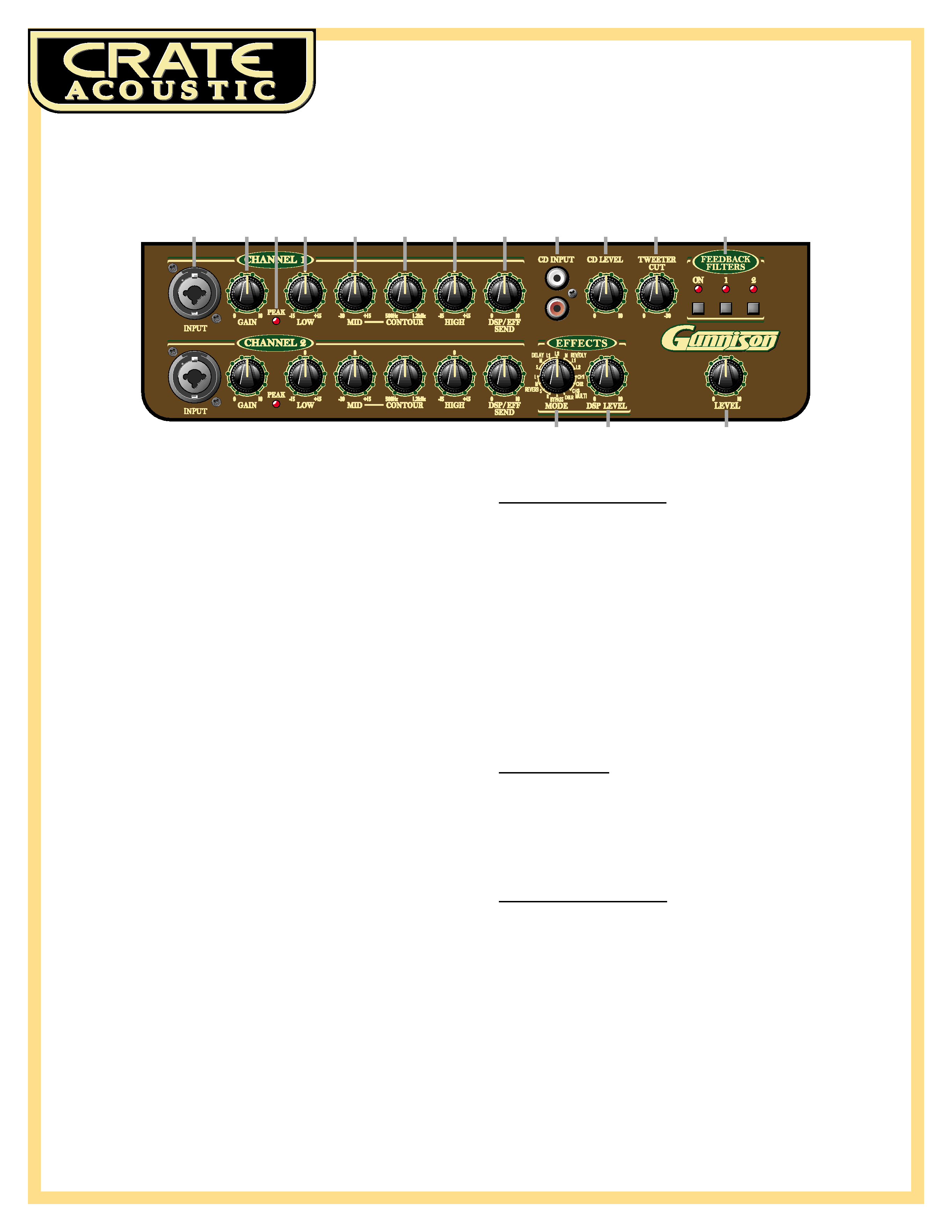
1: Input.
The signal from a low impedance microphone or your acoustic
instrument may be connected here by means of a shielded, balanced
microphone cable terminated with an XLR connector or a shielded
signal cable. This combo jack has 15 volts phantom power applied to
XLR pins 2 and 3. (Mics not requiring phantom power will not be
affected.)
2: Gain.
This serves as the input level control for the Input jack (#1). For
the best signal to noise ratio set this control so the Peak LED (#3)
flashes on strong signals.
3: Peak.
This LED flashes when the signal level into the preamp
approaches clipping. Adjust the Gain control (#2) until a strong sig-
nal causes this LED to flash.
4: Low.
This serves as the bass control. Adjust this control to get the best
sounding bass response for this channel. Excessive boost of the low
control can cause an unnatural howling and should be avoided.
5: Mid.
This serves as the midrange control. Adjust this control to get
the best projection and midrange tones for your instrument. The cen-
ter point of the mid control is chosen by the setting of the Contour
control (#6).
6: Contour.
Use this control to set the center point of the Mid control
(#5). Set this control at the frequency which gives you the most natu-
ral-sounding midrange tones.
7: High.
This serves as the treble control. Adjust this control so your
high notes and harmonic overtones are lively but not overpowering.
8: DSP/Eff Send.
Use this control to adjust the amount of internal
Digital Effect and/or external effect (if used).
The Master Section - part one:
9: CD Input.
Use these RCA jacks to connect a CD or tape player to the
amplifier. Use the CD Level control (#10) to adjust the level of the
player.
10: CD Level.
Use this control to adjust the signal level at the CD Input
jacks (#9).
11: Tweeter Cut.
Use this control to reduce the output level of the inter-
nal high frequency driver. In the fully counter-clockwise position, the
tweeter is at its full output level. As you rotate the control clockwise,
the tweeter level decreases. Adjust this control to best suit your play-
ing environment.
12: Feedback Filters.
Use these switches to activate the CA6110D's
advanced feedback elimination circuitry. For complete details, see the
section entitled "To Eliminate Feedback" on page 6.
The Effects Section:
13: Mode.
Use this control to select the type of Digital Signal Processing
effect applied to the output signal. For a listing of the effects, please
see the section entitled "The DSP Section" on page 6.
14: DSP Level.
Use this control to adjust the amount of internal DSP
effect.
The Master Section - part two:
15: Level.
Use this control to set the overall output level of the amplifier.
The Front Panel:
CA6110D Acoustic Amplifier
5
16
17
18
19
20
21
22
23
24
25
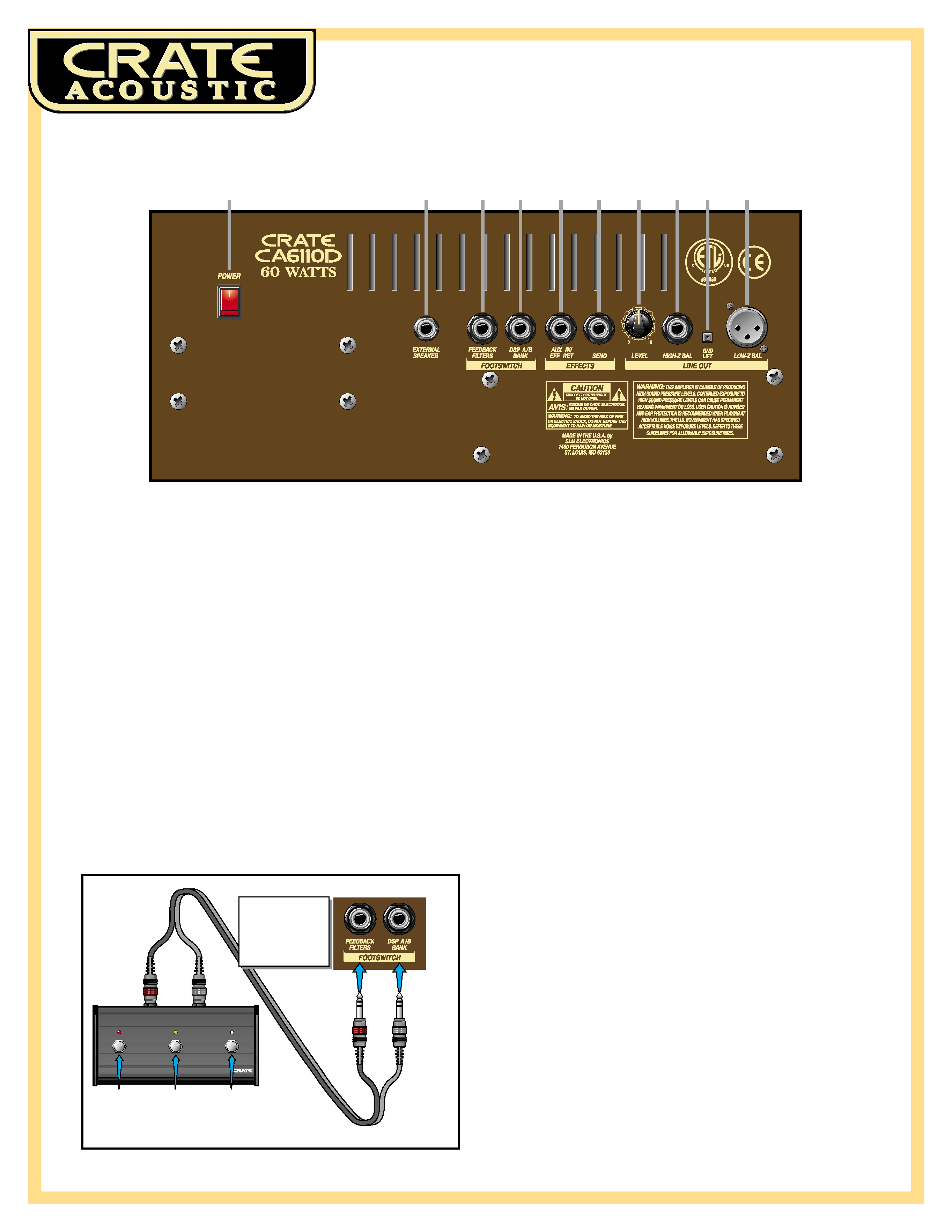
The Rear Panel:
16: Power.
Use this switch to turn the amplifier on (top of the switch
depressed) and off (bottom of the switch depressed.) The power
switch illuminates when the amplifier is on.
17: External Speaker.
Use this jack to connect the amplifier to an external
speaker cabinet. This jack is wired in series with the internal speakers
which remain active when an external speaker is connected.
18: Feedback Filters Footswitch.
Connect the three-button footswitch to
this jack for remote control of the feedback filters. The Feedback
Filters ON LED (#12, front panel) illuminates and the feedback circuit
is activated when a footswitch is connected to this jack. Footswitch
button #1 controls Feedback Filter 1, button #2 controls Filter #2. (See
illustration below.)
Note:
This is a STEREO jack: tip = Filter 1, ring = Filter 2, sleeve is
ground. Use only a footswitch equipped with a stereo 1/4" plug.
19: DSP A/B Bank Footswitch.
Connect the three-button footswitch to
this jack for remote control of two DSP settings:
1.
With footswitch button #3's LED illuminated, select one of the DSP
settings
2.
Step on footswitch button #3 - the LED will go out - select a differ-
ent DSP setting
3.
Step on footswitch button #3 again - the LED illuminates, and the
DSP automatically changes back to the setting chosen in step 1.
4.
Step on footswitch button #3 again - the LED goes out, and the DSP
automatically changes back to the setting chosen in step 2.
20: Effects Aux In/Eff Ret.
When using an external signal processor or any
line level signal (drum machine, keyboard, etc), connect the output of the
device to this jack by means of a shielded signal cable.
21: Effects Send.
When using an external signal processor, connect this
jack to the input of the effect by means of a shielded signal cable.
22: Line Out Level.
Use this control to adjust the output level of the line
out signal. (This control works independently from the amplifier's
master level control.)
23: High Z Bal Line Out.
Use this jack to connect a high impedance, line
level signal to a house sound board, a recording console or an exter-
nal power amplifier by means of an 1/4" stereo plug-terminated
cable. (Ring is signal +, tip is signal -, and sleeve is ground.)
24: Gnd Lift.
This switch, when depressed, electronically disconnects
both of the Line Out jacks' (#23, #25) chassis ground connections. If
you experience excessive noise when using the Line Out jacks,
depress this switch.
25: Low Z Bal Line Out.
Use this jack to connect a low impedance, line
level signal to a house sound board, a recording console or an exter-
nal power amplifier by means of an XLR-terminated cable. (Pin 1 is
ground, pin 2 is signal +, and pin 3 is signal -.)
26: AC Line Cord (not shown).
The grounded power cord should only
be plugged into a grounded power outlet that meets all applicable
electrical codes and is compatible with the voltage, power and fre-
quency requirements stated on the rear panel. Do not attempt to
defeat the safety ground connection!
Button #1:
Turns
Feedback
Filter #1
on and off
Button #2:
Turns
Feedback
Filter #2
on and off
Button #3:
Togg es
between
DSP
settings
CA6110D Rear Panel:
3
2
1
3
2
1
NOTE: The Feedback
circuit is activated
when a footswitch is
plugged into the
Feedback Filters
Footswitch jack ---->