PN-2955H-A
- 1 -
Service Manual
Published by Service Dept.
Printed in Japan
Clarion Co., Ltd.
7-2, Shintoshin, Chuo-ku, Saitama-shi, Saitama 330-0081 Japan
Service Dept.: 7-2, Shintoshin, Chuo-ku, Saitama-shi, Saitama 330-0081 Japan
Tel: +81-48-601-3705 FAX: +81-48-601-3804
298-6542-00 Feb.2008
Model
NISSAN Motor Genuine
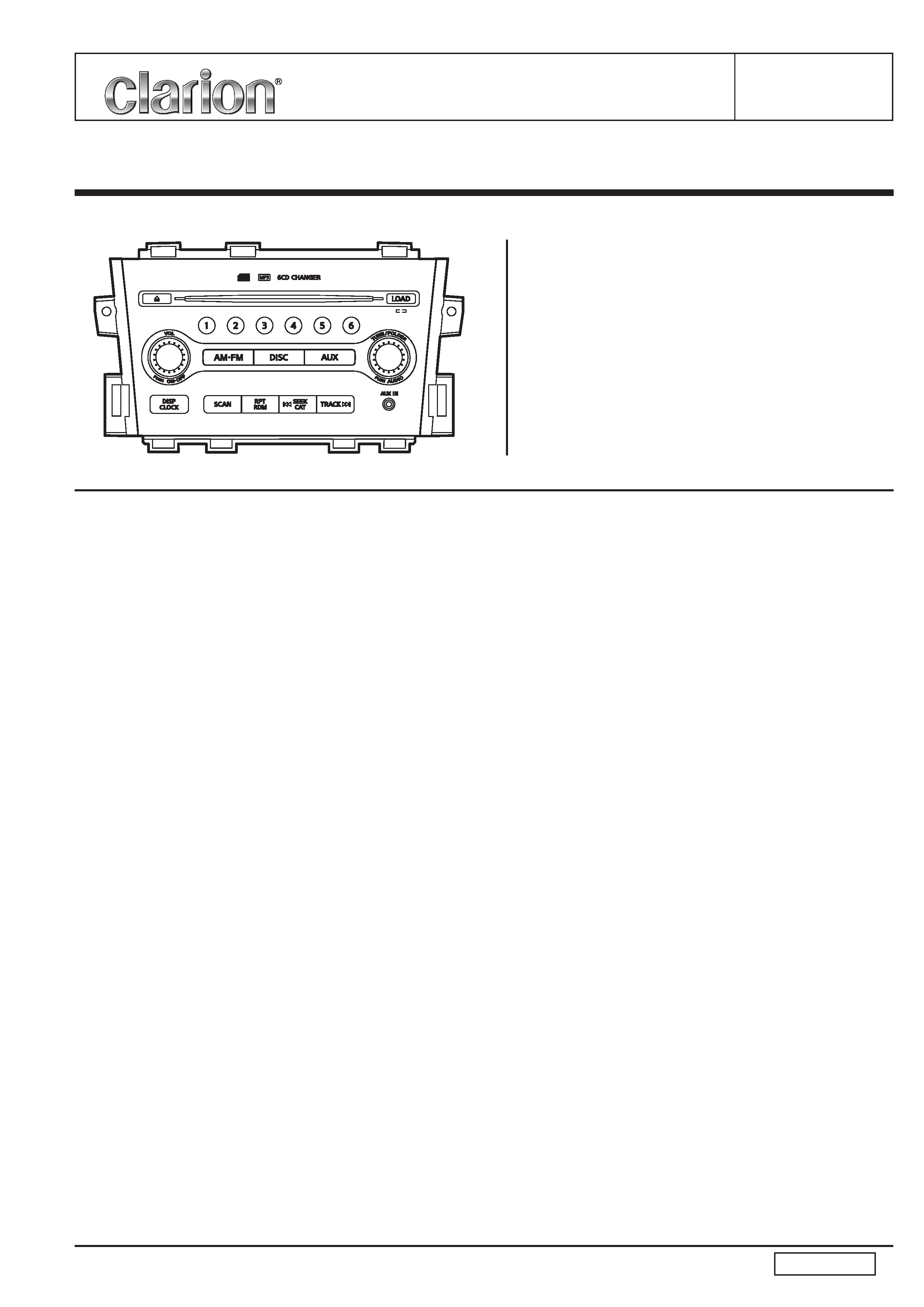
6CD AM/FM Radio Combination
PN-2955H-A
(Genuine No.28185 1AA0A)
(ID No. CY25D)
NOTES
*
The tuner of this unit is BUS-TUNER type. When the
tuner pack(BL101) is exchanged, it is necessary to ad-
just for S-meter etc. with special JIG.
*
Individual data of each unit is recorded in EEPROM
IC(IC401). When EEPROM IC is replaced, it is neces-
sary to write the data.
*
DSP IC(IC301) is fixed with solder. Special JIG is nec-
essary for removing it.
*
This product includes technology owned by Microsoft
Corporation and cannot be used or distributed without a
license from MSLGP.
*
We cannot supply PWB with component parts in prin-
ciple. When a circuit on PWB has failure, please repair it
by component parts base. Parts which are not mentioned
in service manual are not supplied.
*
Specifications and design are subject to change without
notice for further improvement.
CD Player section
Mechanism:
6Disc CD Auto Changer
Disc:
12cm Disc
Format:
CD-DA,MP3,WMA
Distortion:
Less than 0.2%(1kHz,20kHz L.P.F.)
MP3 sampling rate:
8kHz to 48kHz
MP3 bit rate:
8kbps to 320kBps/VBR
WMA bit rate:
32kbps to 192kBps/VBR
Logical format:
ISO9660 Level 1,2
Romeo or Joliet
S/N ratio:
More than 74dB
(1kHz,0dB=4.5V,20kHz L.P.F)
Separation:
More than 50dB
(1kHz,20kHz L.P.F)
AUX section
Distortion:
Less than 0.4%(Input 1kHz 300mV,
Output 2.45V=0dB)
S/N ratio:
More than 65dB(Input 1kHz 300mV,
Output 4.5V=0dB)
Separation:
More than 52dB(Input 1kHz
300mV[L or R],Output 2.45V=0dB)
General
Load impedance:
2ohm/4CH
Power output:
45W x 4 Type
Power supply voltage: DC13.2V(10.8 to 15.6V)
Negative ground
Back-up consumption: Less than 1.0mA
Dimensions(mm):
242(W) x 145(H) x 190(D)
Weight:
2.4kg
COMPONENT
PN-2955H-A
1.
Main unit
----------
1
SPECIFICATIONS
Radio section
Tuning system:
PLL Frequeency synthesizer system
Receive range:
AM 530kHz to 1,710kHz
FM 87.75MHz to 107.9MHz
Quieting sensitivity:
AM Less than 37dBuV(S/N=20dB)
FM Less than 15dBuV(at 30dB S/N)
Separation:
FM More than 25dB
(ANT IN 65dBuV,1kHz)
More than 20dB
(ANT IN 65dBuV,7kHz)
S/N ratio:
AM More than 40dB
(ANT IN 74dBuV,0dB=1.4V)
FM More than 50dB
(ANT IN 55dBuV,0dB=1.4V)
Auto tuning stop sensitivity:
AM 39 +6/-6dBuV
FM 32 +6/-6dBuV
PN-2955H-A
- 2 -
To engineers in charge of repair or
inspection of our products.
Before repair or inspection, make sure to follow the
instructions so that customers and Engineers in charge
of repair or inspection can avoid suffering any risk or
injury.
1. Use specified parts.
The system uses parts with special safety features against fire
and voltage. Use only parts with equivalent characteristics
when replacing them.
The use of unspecified parts shall be regarded as remodeling
for which we shall not be liable. The onus of product liability
(PL) shall not be our responsibility in cases where an accident
or failure is as a result of unspecified parts being used.
2. Place the parts and wiring back in their original positions after
replacement or re-wiring.
For proper circuit construction, use of insulation tubes, bond-
ing, gaps to PWB, etc, is involved. The wiring connection and
routing to the PWB are specially planned using clamps to keep
away from heated and high voltage parts. Ensure that they are
placed back in their original positions after repair or inspec-
tion.
If extended damage is caused due to negligence during re-
pair, the legal responsibility shall be with the repairing com-
pany.
3. Check for safety after repair.
Check that the screws, parts and wires are put back securely
in their original position after repair. Ensure for safety reasons
there is no possibility of secondary ploblems around the re-
paired spots.
If extended damage is caused due to negligence of repair, the
legal responsibility shall be with the repairing company.
4. Caution in removal and making wiring connection to the parts
for the automobile.
Disconnect the battery terminal after turning the ignition key
off. If wrong wiring connections are made with the battery con-
nected, a short circuit and/or fire may occur. If extensive dam-
age is caused due to negligence of repair, the legal responsi-
bility shall be with the repairing company.
5. Cautions in soldering
Please do not spread liquid flux in soldering.
Please do not wash the soldering point after soldering.
6. Cautions in soldering for chip capacitors
Please solder the chip capacitors after pre-heating for replace-
ment because they are very weak to heat.
Please do not heat the chip capacitors with a soldering iron
directly.
7. Cautions in handling for chip parts.
Do not reuse removed chips even when no abnormality is ob-
served in their appearance. Always replace them with new
ones. (The chip parts include resistors, capacitors, diodes, tran-
sistors, etc).
Please make an operation test after replacement.
8. Cautions in handling flexible PWB
Before working with a soldering iron, make sure that the iron
tip temperature is around 270
. Take care not to apply the
iron tip repeatedly(more than three times)to the same patterns.
Also take care not to apply the tip with force.
9. Turn the unit OFF during disassembly and parts replacement.
Recheck all work before you apply power to the unit.
10. Cautions in checking that the optical pickup lights up.
The laser is focused on the disc reflection surface through the
lens of the optical pickup. When checking that the laser opti-
cal diode lights up, keep your eyes more than 30cms away
from the lens. Prolonged viewing of the laser within 30cms
may damage your eyesight.
11. Cautions in handling the optical pickup
The laser diode of the optical pickup can be damaged by elec-
trostatic charge caused by your clothes and body. Make sure
to avoid electrostatic charges on your clothes or body, or dis-
charge static electricity before handling the optical pickup.
11-1. Laser diode
The laser diode terminals are shorted for transportation in or-
der to prevent electrostatic damage. After replacement, open
the shorted circuit. When removing the pickup from the mecha-
nism, short the terminals by soldering them to prevent this
damage.
11-2. Actuator
The actuator has a powerful magnetic circuit. If a magnetic
material is put close to it. Its characteristics will change. En-
sure that no foreign substances enter through the ventilation
slots in the cover.
11-3. Cleaning the lens
Dust on the optical lens affects performance.
To clean the lens, apply a small amount of isopropyl alcohol to
lens paper and wipe the lens gently.
CAUTION
Use of controls, adjustment, or performance of procedures
other than those specified herein, may result in hazardous
radiation exposure. The compact disc player should not be
adjusted or repaired by anyone except properly qualified
service personnel.
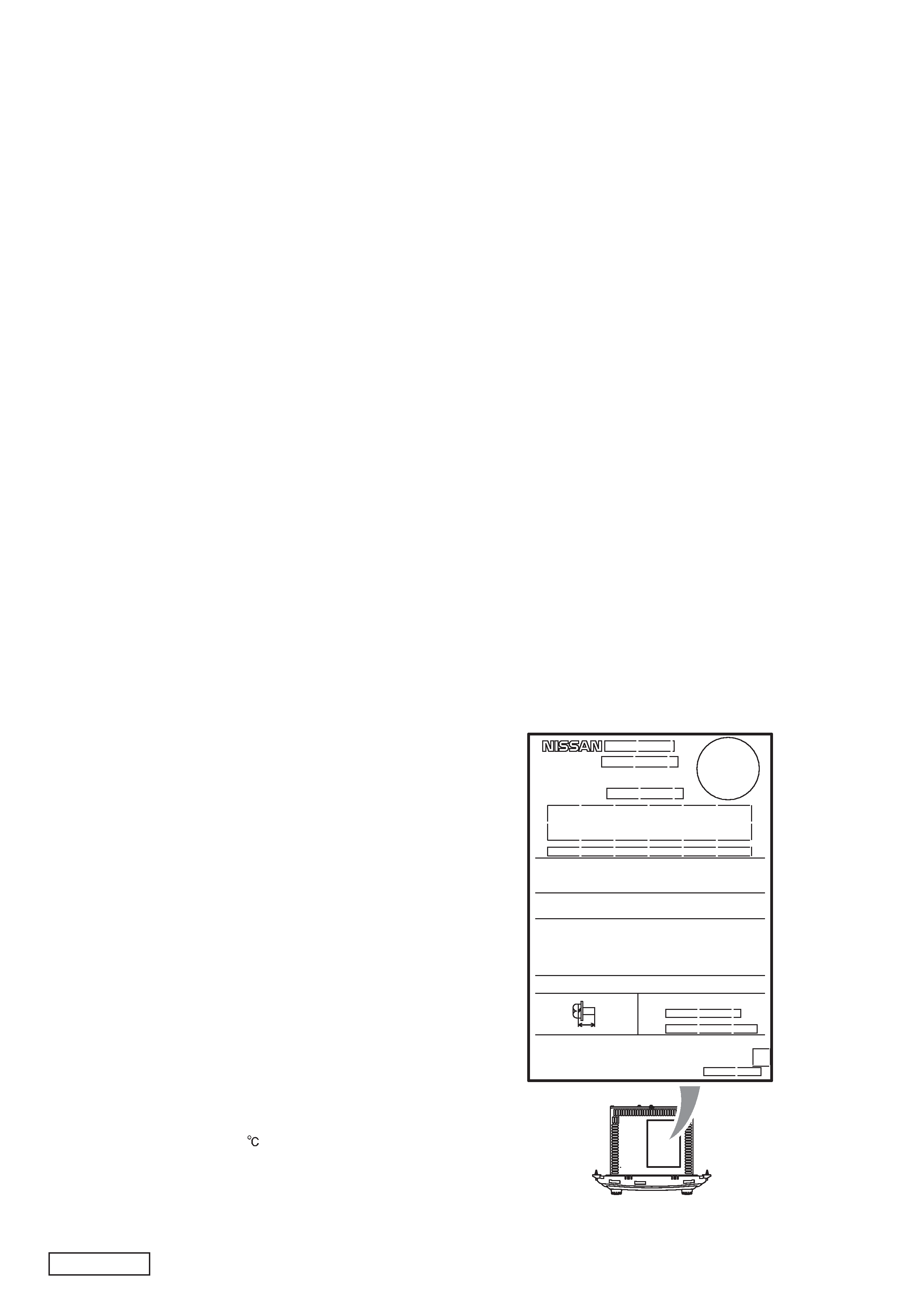
SERIAL NO.
MANUFACTURED
AM:
PART No.
FM:
FREQUENCY RANGE
THIS DEVICE COMPLIES WITH PART 15 OF THE FCC
RULES. OPERATION IS SUBJECT TO THE FOLLOWING
TWO CONDITOINS:(1) THIS DEVICE MAY NOT CAUSE
HARMFUL INTERFERENCE,AND(2) THIS DEVICE MUST
ACCEPT ANY INTERFERENCE RECEIVED,INCLUDING
INTERFERENCE THAT MAY CAUSE UNDESIRED
OPERATION.
THIS PRODUCTION COMPLIES WITH DHHS RULES 21 CFR
SUBCHAPTER J APPLICABLE AT DATE OF MANUFACTURE.
MODEL NO.
12V(-)GROUND
This product includes technology oned by
Microsoft Corporation and cannot be used or distributed
without a license from MSLGP.
ongguan Clarion Orient Electronics Co.,Ltd.
Junda Industrial Zone,Dong Keng Industrial Road,Dong Keng
Town Dongguan,Guangdong Province 511734,The People's
Republic of China
MADE IN CHINA
MOUNT SCREW
M5X8 mm MAX
ISO
Setplate
Top of view
PN-2955H-A
- 3 -
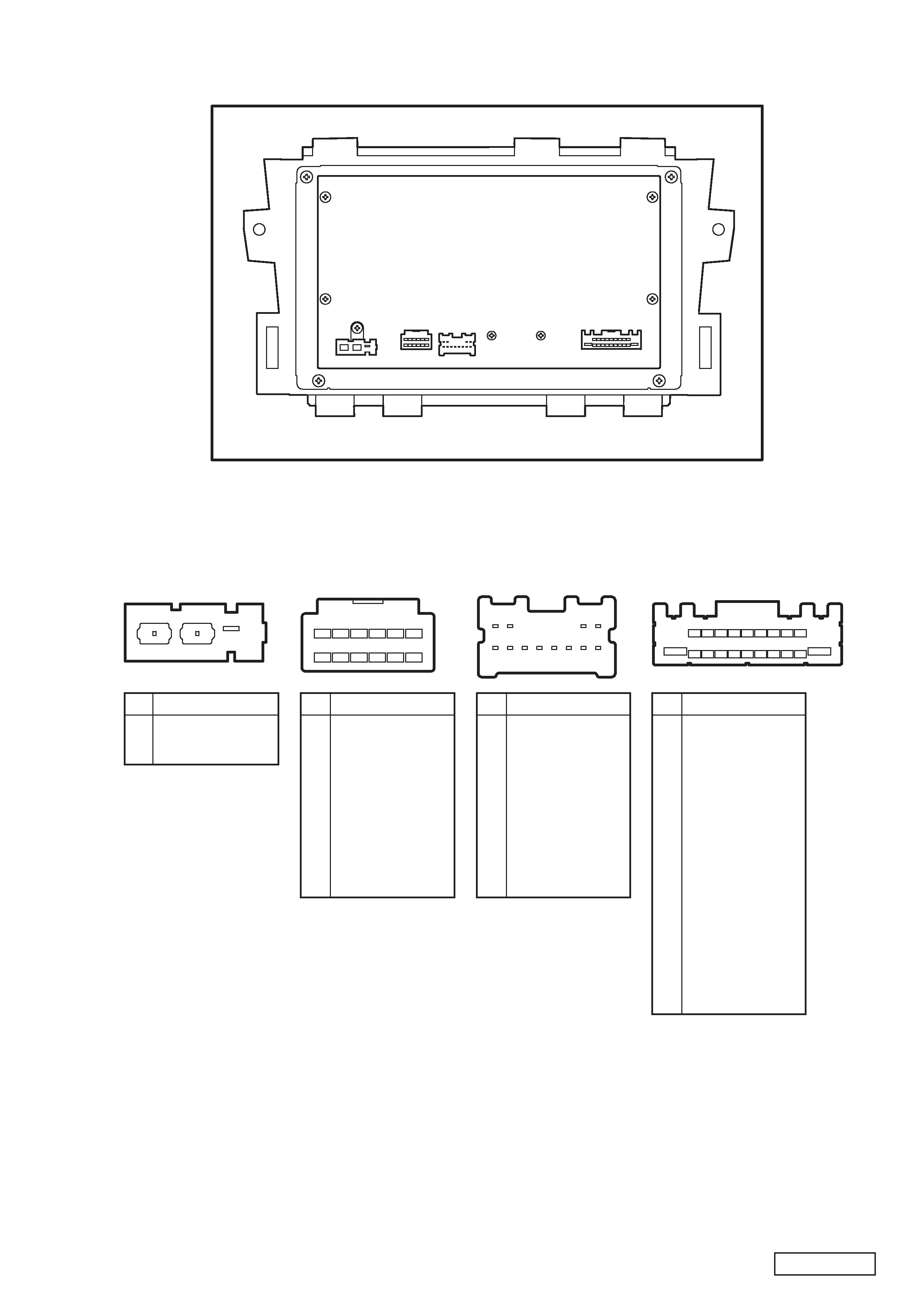
CONNECTIONS
ANT101 (GT13)
ANT Connector
Rear View
C
B
A
h11 h12 h13 h14 h15 h16
h17 h18 h19 h20 h21 h22
J602 (TH12)
M-CAN Connector
(for Display unit)
J601 (A12)
N-BUS Connector
(for Satellite radio)
V02 V04
V10 V12
V01
V03
V05
V06
V07
V08
V09
V11
1 2 34 5 67 89
19
10 11 12 13 14 15 16 17 18 20
J501 (TH18 )
Main Connector
No. Pin Name
A
B
C
ANT+B
MAIN ANT
SUB ANT
No. Pin Name
h11
h12
h13
h14
h15
h16
h17
h18
h19
h20
h21
h22
M CAN (-)
M CAN (+)
N.C.
N.C.
N.C.
N.C.
M CAN SHIELD
GND
N.C.
N.C.
N.C.
GND
No. Pin Name
V1
V2
V3
V4
V5
V6
V7
V8
V9
V10
V11
V12
SAT LCH (-)
SAT LCH (+)
SAT RCH (-)
SAT RCH (+)
GND
SHIELD GND
N.C.
REQ(SAT->COMBI)
RXD(SAT->COMBI)
TXD(COMBI->SAT)
N.C.
N.C.
No. Pin Name
1
2
3
4
5
6
7
8
9
10
11
12
13
14
15
16
17
18
19
20
N.C.
FRONT LCH (+)
FRONT LCH (-)
REAR LCH (+)
REAR LCH (-)
STRG SW A
ACC
ILL CONT
ILL (+)
B/U
GND
FRONT RCH (+)
FRONT RCH (-)
REAR RCH (+)
REAR RCH (-)
STRG GND
STRG SW B
N.C.
N.C.
GND
J501
J601
J602
ANT101
PN-2955H-A
- 4 -
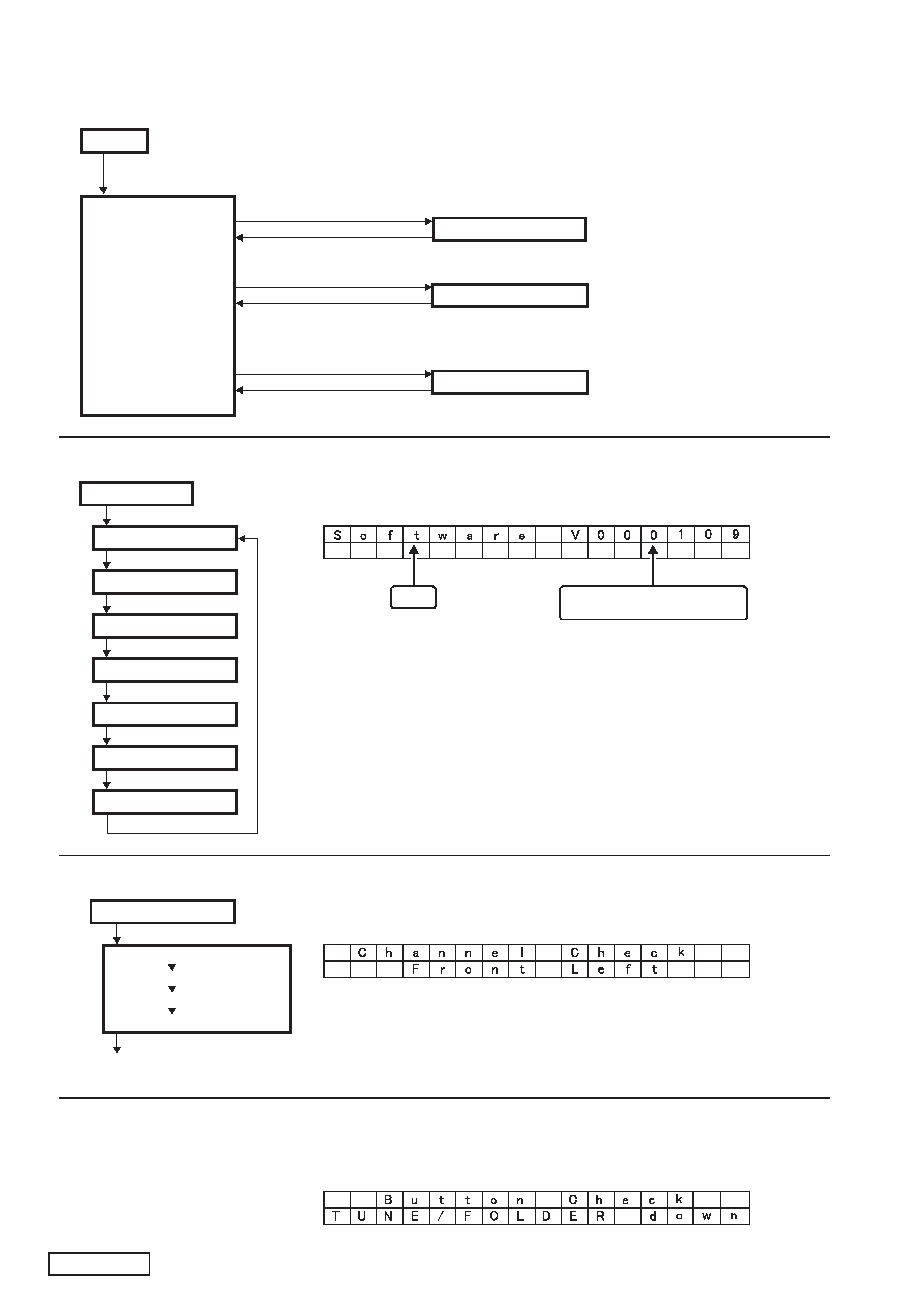
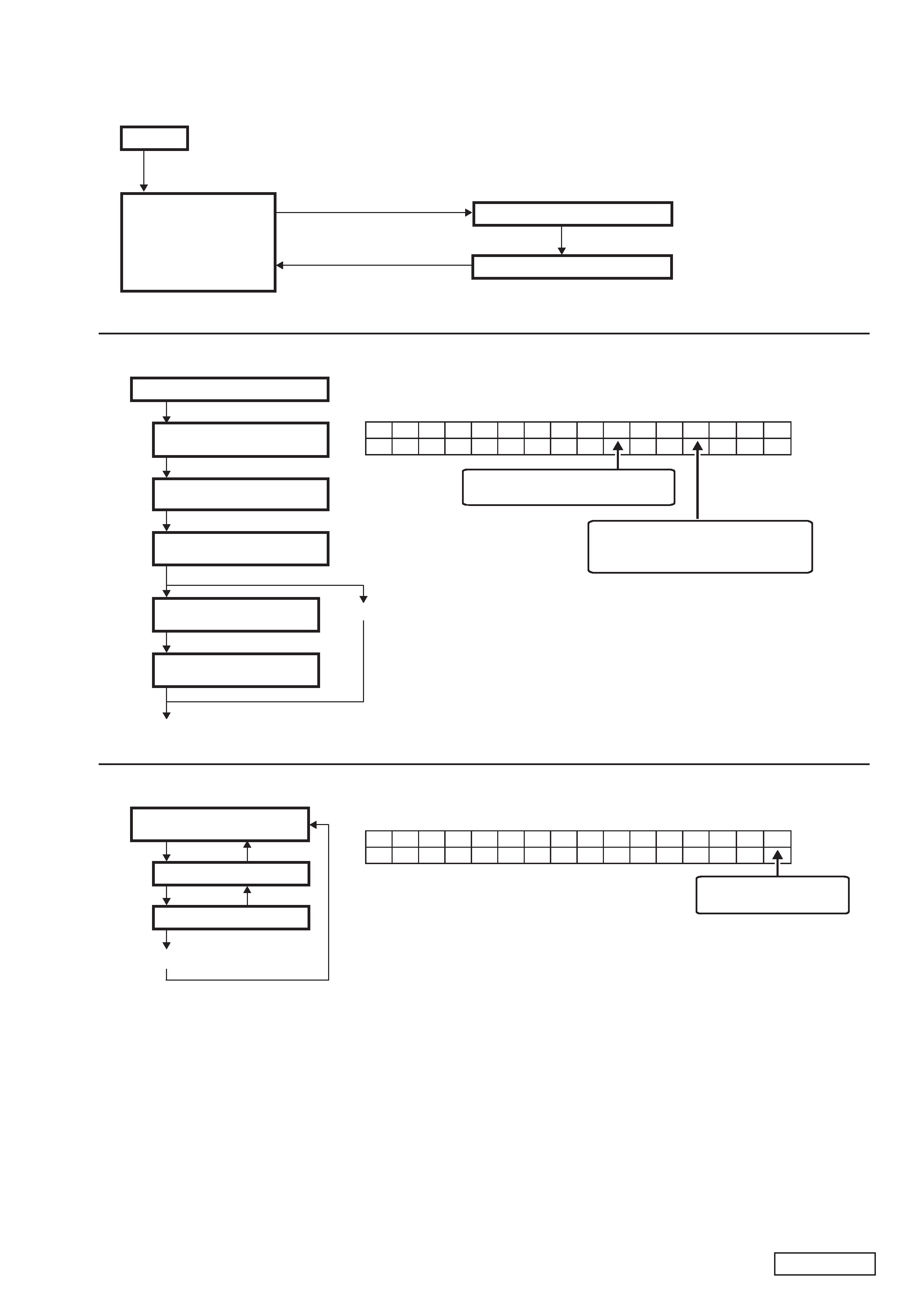
DIAGNOSIS
Power off
Self-diagnosis mode
(Mode release: Acc-off)
Self-diagnosis mode
(Mode release: Acc-off)
Click the VOL key 30 times right and left while pressing "1" key.
(1-1) Version check mode
(1-2) Channel check mode
AUDIO key
AUDIO key(for several seconds)
AUDIO key(for several seconds)
or Time out(1second)
AUDIO key
AUDIO key
AUDIO key
AUDIO key
AUDIO key
AUDIO key
AUDIO key
AUDIO key
Version check mode
(1-1) Version check mode
(1) Self-diagnosis mode
Software version
Software version display
Item
Hardware version
CD mech. software version
EEP version
Display software version
Display hardware version
Satellite radio version
(1-2) Channel check mode
Channel check mode
Front Left (Beep 1.0kHz/1sec.)
Front Right (Beep 1.0kHz/1sec.)
Rear Right (Beep 1.0kHz/1sec.)
Rear Left (Beep 1.0kHz/1sec.)
Version
"VFFFFFF" : Unconnection
Front Left check display
* In the button check mode, when each key is operated, the key name is displayed.
The beep sound(3.5kHz) rings when the key is operated.
(1-3) Button check mode
TUNE/FOLDER down check display
Turn TUNE/FOLDER key right
(1-3) Botton check mode
AUDIO key(for several seconds)
Turn TUNE/FOLDER key left
PN-2955H-A
- 5 -
Click the VOL key 30 times right and left while pressing "6" key.
AUDIO key
AUDIO key
AUDIO key
AUDIO key
AUDIO key
AUDIO key
Error record display mode
Error record reset mode
"AV TROUBLE DEL"
M-CAN transmission count display
"TRANSMIT $$ ##"
M-CAN transmission count display
T
R
A
N
S
M
I
T
$$
##
CMF reception error from Display
"DISP $$ ##"
MPDT error from display
"DISP MPDT $$ ##"
TRACK >>| key
After 6 sec.
TRACK >>| key
|<< SEEK key
(The record is cleared)
"RECORD DEL-NO?"
"RECORD DEL-YES?#"
CMF reception error from BTHF
"BTHF $$ ##"
MPDT error from BTHF
"BTHF MPDT $$ ##"
Error record rest mode (2-2)
"NO HISTORY BTHF"
(at BT unconnection)
"##"
Past diagnosis result:
"OK" / "0" - "39" (NG counter)
"$$"
Current diagnosis result: "OK" / "UN"
Error record reset display
RE
C
O
RD
E
DL
Y
?
#
-E
S
"#"
Countdown time: "6" - "0"
Power off
Communication
diagnosis mode
(Mode release: Acc-off)
(2-1) Error record display mode
(2-2) Error record reset mode
AUDIO key
AUDIO key
AUDIO key
(2-1) Error record display mode
(2) Communication diagnosis mode
(2-2) Error record reset mode