SA-65
SA-65
ON
OFF
POWER
VOLUME
START/STOP
MELODY OFF
TEMPO
TONE
PATTERN
SONG
BANK
78
9
45
6
1
0
23
MUSICAL INFORMATION SYSTEM
VOLUME
TEMPO
TONE
PATTERN
SONG BANK
10 SONG BANK
ELECTRONIC KEYBOARD

CONTENTS
Specifications . . . . . . . . . . . . . . . . . . . . . . . . . . . . . . . . . . . . . . . . . . 1
Block Diagram . . . . . . . . . . . . . . . . . . . . . . . . . . . . . . . . . . . . . . . . . 2
Circuit Description . . . . . . . . . . . . . . . . . . . . . . . . . . . . . . . . . . . . . . . . 2
Waveforms . . . . . . . . . . . . . . . . . . . . . . . . . . . . . . . . . . . . . . . . . . 5
Printed Circuit Board . . . . . . . . . . . . . . . . . . . . . . . . . . . . . . . . . . . . . . 6
Schematic Diagrams . . . . . . . . . . . . . . . . . . . . . . . .. . . . . . . . . . . . . . 7
Exploded View . . . . . . . . . . . . . . . . . . . . . . . . . . . . . . . . . . . . . . . . . 9
Parts List . . . . . . . . . . . . . . . . . . . . . . . . . . . . . . . . . . . . . . . . . 11
-- 1 --
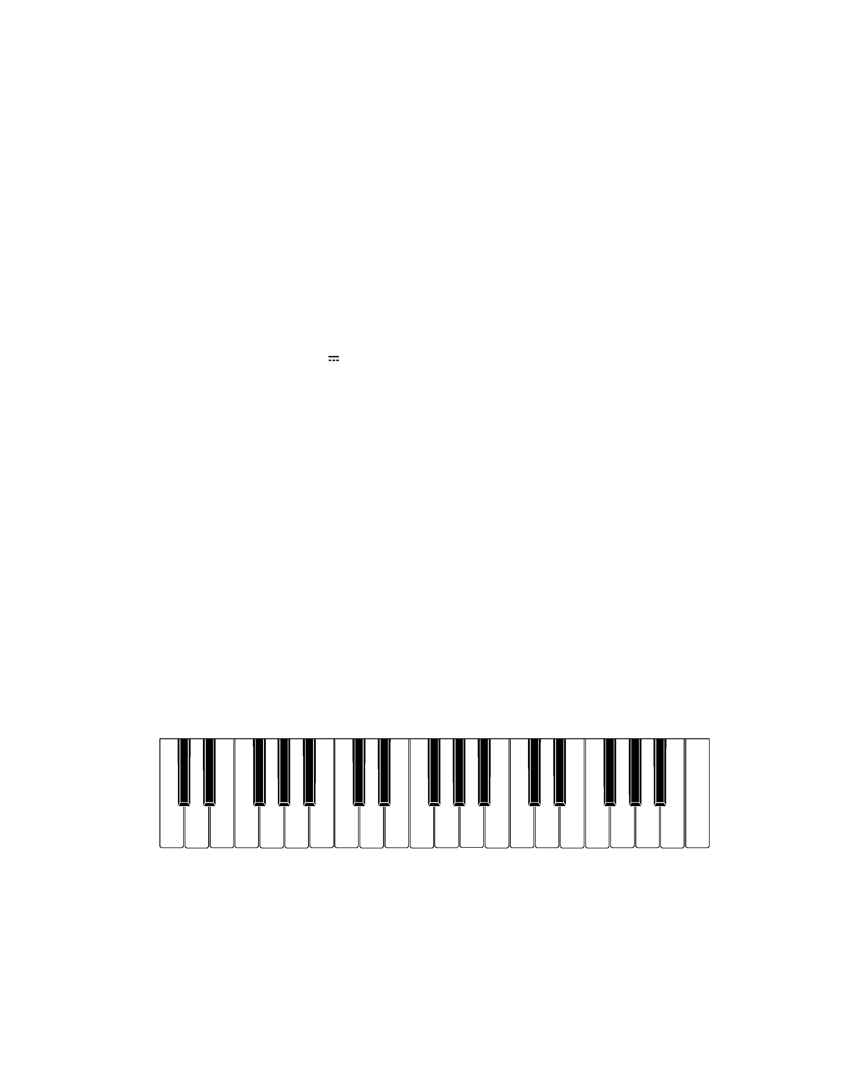
C#3
C3 D3 E3
F3
G3 A3
B3
C4 D4 E4
F4
G4 A4
B4
C5 D5 E5
F5
G5 A5
B5
C6
D#3
F#3 G#3 A#3
C#4 D#4
F#4 G#4 A#4
C#5 D#5
F#5 G#5 A#5
ELECTRICAL
Current drain with 7.5 V DC:
No sound output
33 mA
± 20 %
Maximum volume
230 mA
± 20 %
with keys G3, A#3, B3 and C4 pressed
in Car Horn tone, Volume: Maximum
Speaker output level
1060 mV
± 20 %
with key C2 pressed in Street Organ tone
Volume: Maximum
Minimum operating voltage:
5.5 V
SPECIFICATIONS
GENERAL
Keyboard:
37 keys, 3 octaves (mini-size)
Polyphony:
4 notes maximum
Tones:
100
Patterns:
30 (RHYTHM, FREE SESSION, FUNNY)
Song band:
10 tunes; melody off
Tuning:
Fixed; A4 = approx. 442 Hz
Speakers:
Two; 8.0cm (output: 0.5 W + 0.5 W)
Input terminals:
AC adaptor (7.5 V DC)
Power supply:
Two-way
Five AA-size batteries
Battery Life: Approximately six hours on R6P (SUM-3) manganese batteries
AC Adaptor (AD-1)
Power consumption:
7.5 V
2.3 W
Dimensions (HWD):
74
× 650 × 211 mm
(2-15/16
× 25-5/8 × 8-5/16 inches)
Weight:
Approximately 1.6 kg (3.53 lbs) (without batteries)
Nomenclature of Keys
-- 2 --
KI0
KI1
KI2
KI3
KI4
KI5
KI6
KI7
KO0
C3
C#3
D3
D#3
E3
KO1
F3
F#3
G3
G#3
A3
A#3
B3
C4
KO2
C#4
D4
D#4
E4
F4
F#4
G4
G#4
KO3
A4
A#4
B4
C5
C#5
D5
D#5
E5
KO4
F5
F#5
G5
G#5
A5
A#5
B5
C6
KO5
0
1
2
3
4
Tempo
Melody
Up
Off
KO6
5
6
789
Volume
Tempo
Up
Down
KO7
Song
Pattern
Tone
Start/
Volume
Bank
Stop
Down
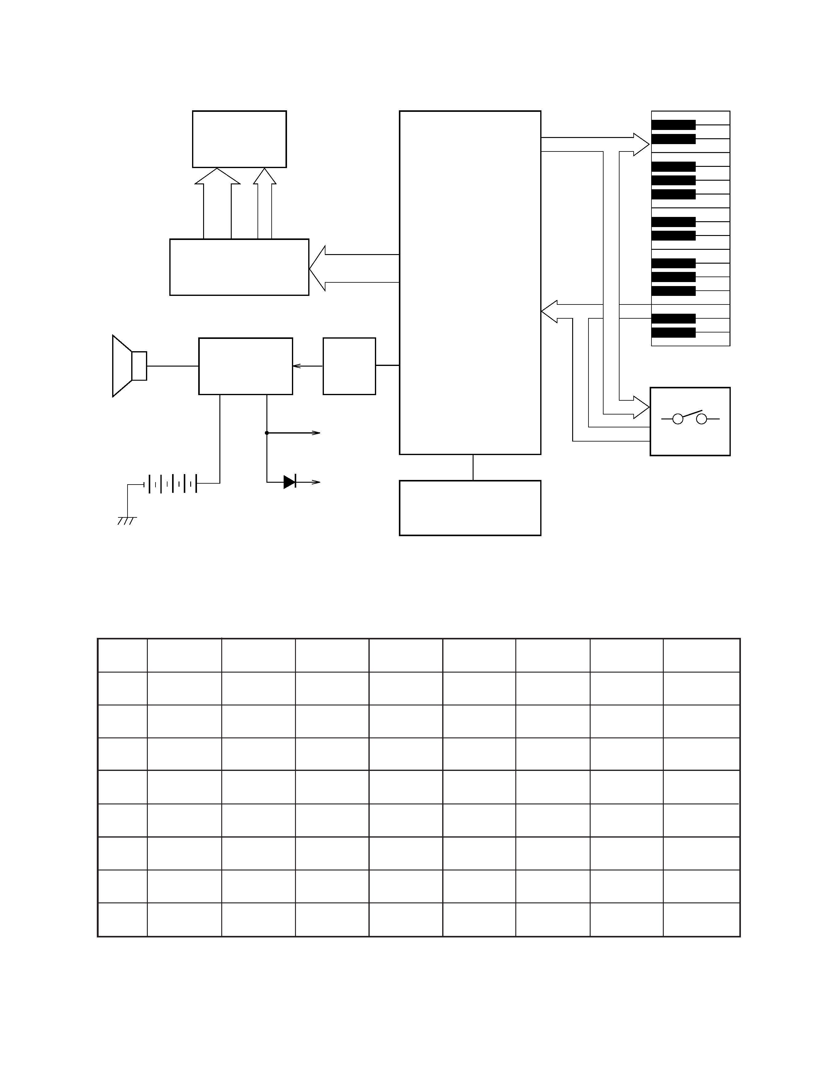
BLOCK DIAGRAM
CIRCUIT DESCRIPTION
Key Matrix
KO0 ~ KO7
KI0 ~ KI7
Keyboard
Switches
Oscillator
Q102, X101
CPU
MSM6387B-A28
LSI101
Amplifier
AN8053N
IC101
Speaker
VDD
KO8 ~ KO11
COM1, COM2
Q101
Filter
S1 ~ S14
S18 ~ S20
S31 ~ S46
OUT
LCD Driver
KS0035
IC102
LCD
-- 3 --
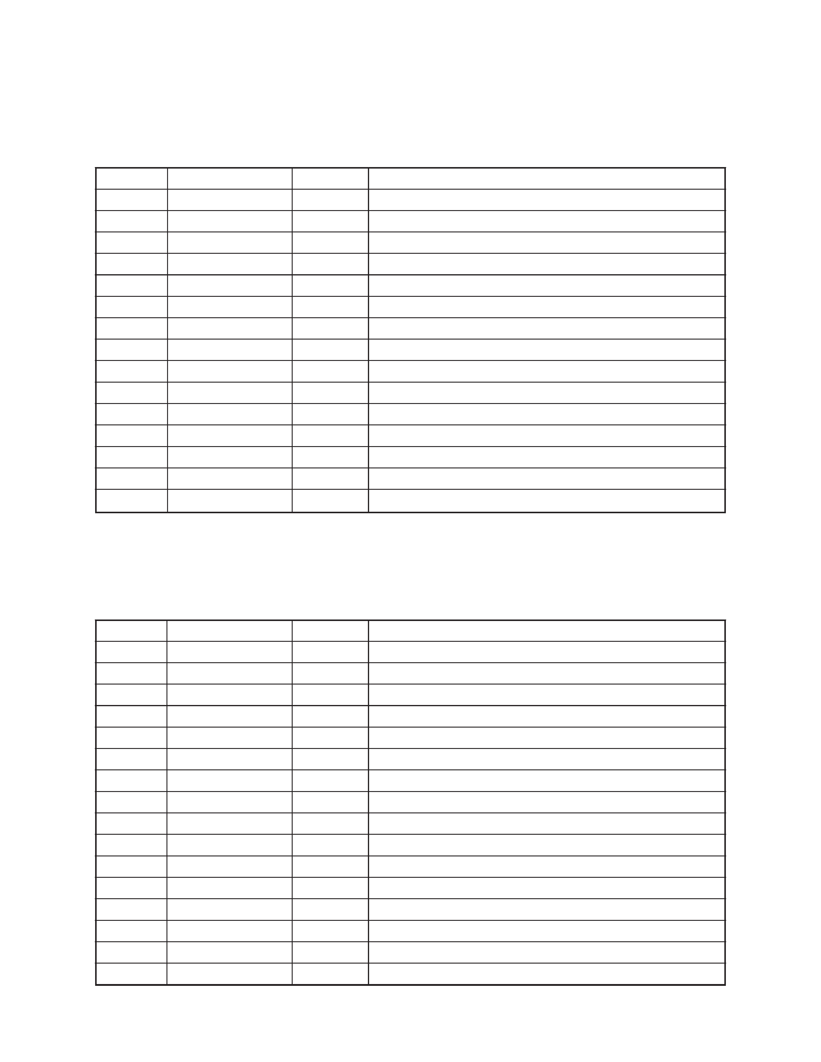
LCD Driver (IC102 : KS0035)
The KS0035 is an LCD driver for a segment type LCD, and it can drive up to 53 segments.
The following table shows the pin functions of IC102.
Pin No.
Terminal
In/Out
Function
1, 2
TEST1, TEST2
--
Not used. Connected to ground.
3
RESET
In
Power ON reset terminal. On: +5 V Off: 0 V
4
AVDD
In
+5 V source for the built-in DAC
5
OUT
Out
Sound waveform output
6
AGND
In
Ground (0 V) source for the built-in DAC
7
GND
In
Ground (0 V) source
8
COSI
In
21.725 MHz clock pulse input
9
COSO
--
Not used
10
VDD
In
+5 V source
11 ~ 18
KI0 ~ KI7
In
Input terminals from keys and switches
19
KO11
Out
Display data output
20
KO10
Out
Bit clock output
21
KO9
Out
Chip enable signal for the LCD driver
22
KO8
Out
Display blanking output
23 ~ 30
KO7 ~ KO0
Out
Key scan signal outputs
CPU (LSI101: MSM6387B-A28)
Containing a sound data ROM and a DAC (Digital to Analog Convertor), the CPU provides sound waveform
in accodance with the pressed key and the selected tone.
The following table shows the pin functions of LSI101.
Pin No.
Terminal
In/Out
Function
1 ~ 14
S1 ~ S14
Out
Segment output
15 ~ 17
S15 ~ S17
--
Not used
18 ~ 20
S18 ~ S20
Out
Segment output
21 ~ 30
S21 ~ S29
--
Not used
31 ~ 47
S30 ~ S46
Out
Segment output
36
S35
--
Not used
48 ~ 54
S47 ~ S53
--
Not used
55
OSC
In
Terminal for the internal clock generator
56
VDD
In
+5 V source
57
INH
In
Display blanking input
58
VLCD
In
+5 V source for the internal driver
59
VSS
In
Ground (0 V) source
60
CE
In
Chip enable input
61
CLK
In
Bit clock input
62
DATA
In
Display data input
63, 64
COM1, COM2
Out
Common out put