ELECTRONIC CASH REGISTER
QT-2000
(EX-580)
JUNE 1997
C
7
4
1
0
8
5
2
00
9
6
3
¥
SERVICE MANUAL
(without price)

CONTENTS
QT-2000
Page
1. GENERAL ............................................................................................................... 1
1-1. System chart .................................................................................................... 1
1-2. Device list (Option) .......................................................................................... 2
2. SPECIFICATIONS ................................................................................................. 3
3. QT-2000 CONNECTOR LOCATIONS .................................................................... 8
4. INITIALIZE OPERATION ...................................................................................... 11
4-1. To initialize QT-2000 terminal ........................................................................ 11
4-2. To initialize QT-2000 terminal(add/replace one QT-2000) ............................ 14
4-3. To flag clear QT-2000 terminal(INIT2, Restore from flash) ........................... 17
5. CIRCUIT EXPLANATION ..................................................................................... 18
5-1. Block diagram (MAIN PCB E580-1)............................................................... 18
5-2. Memory map .................................................................................................. 19
5-3. I/O address map ............................................................................................ 20
5-4. LSI Pin description ......................................................................................... 21
5-5. Power down detection circuit ......................................................................... 33
5-6. Option RAM circuit ......................................................................................... 34
6. OPTION INSTALLATION ...................................................................................... 35
6-1. Clerk key unit (CLK-K17,CLK-K18) ............................................................... 35
6-2. Rear display (QT-2060D)............................................................................... 36
6-3. MCR unit (QT-2046MC) ................................................................................. 37
6-4. Multi drawer (MDL-8) ..................................................................................... 38
7.IN / ON LINE .......................................................................................................... 39
7-1. C-In line (ARCNET) ....................................................................................... 39
7-2. On line ........................................................................................................... 42
1. Direct connection to PC ................................................................................. 42
2. MODEM system ............................................................................................. 43
7-3. Kitchen printer connection ............................................................................. 44
8.DIAGNOSTIC OPERATION ................................................................................... 47
9.ERROR CODE LIST .............................................................................................. 67
10.IC DATA ............................................................................................................... 73
11.PCB LAYOUT ...................................................................................................... 80
12.CIRCUIT DIAGRAM ............................................................................................. 82
13. PARTS LIST ...................................................................................................... 104
-- 1 --
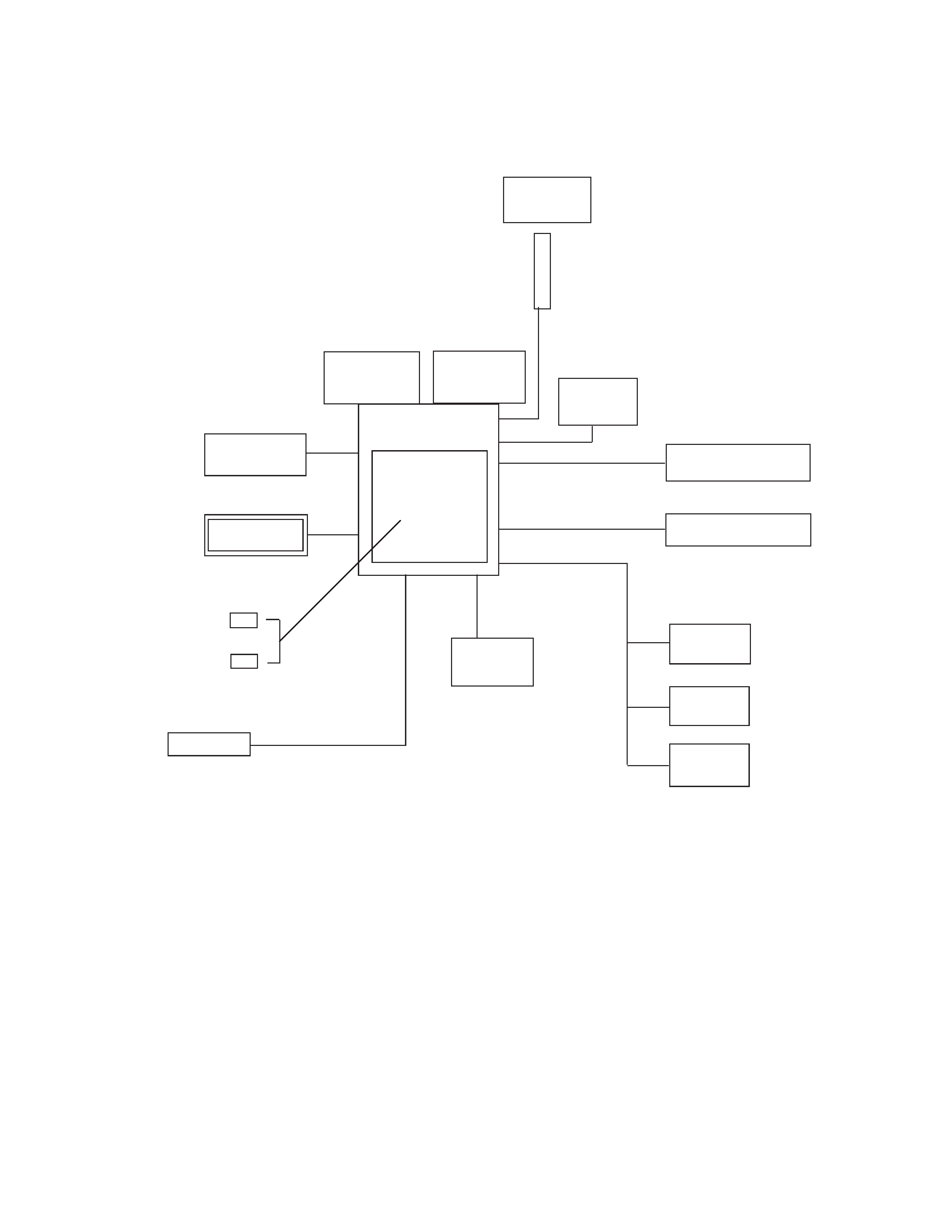
The QT-2000 has the following unique points:
(The system configuration is shown in the chart above.)
1. Separete R/J printer
2. Small foot-print and low-profile design
3. LCD display : Max. 2 LCD display
4. Flat keyboard menu holder : Max. 8 menu can be contorolled.
4 (direction) x 2 (holder)
5. Data backup function by EEPROM (Flash ROM)
6. Infrared communication interface
2nd Display
QT-2000
Cable
SA-1062S
Kitchen Printer
KP-200 / KP-300
R/J Printer
TM-U950
TM-T85
TM-T88
SA-3015
TM-T85
UP-350
Clerk Key
CLK-K17 (6 clerk)
CLK-K18 (15 clerk)
MCR unit
Multi Drawer
MDL-8
QT-2046MC
RAM610
4M bits
RAM530
1M bits
Slip Printer
SP-1200
Scanner
HHS-9
1. GENERAL
1-1. System chart
Customer
Display
Pole
QT-2063D
QT-2061S
Rear
Display
QT-2060D
-- 2 --
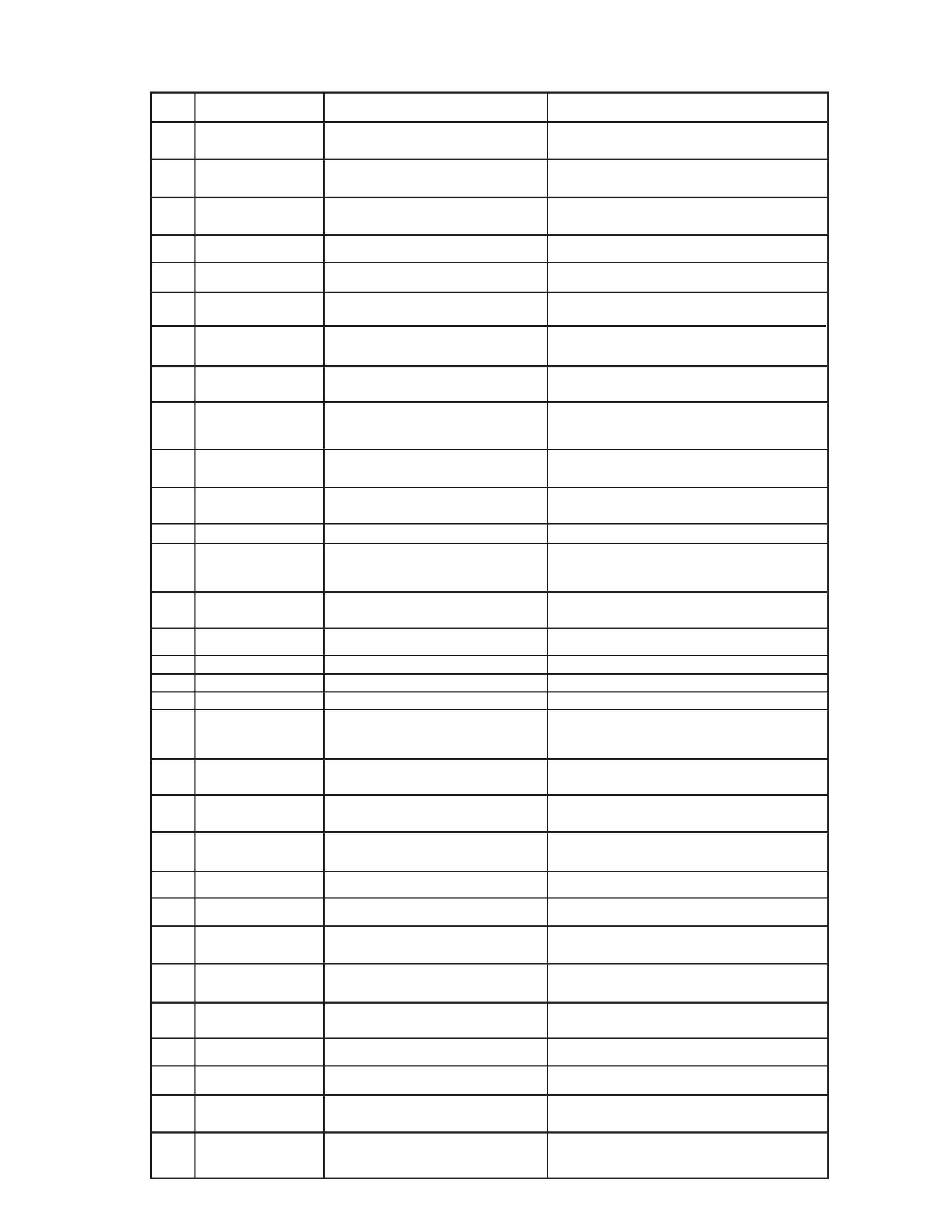
1-2. Device list (Option)
No.
Model Name
Device Name
Note
Sheet holder
1
SH-KIT1
Sheet holder kit
2 holders (1st - 4th, 5th - 8th)
Kitchen Printer
2
KP-200
Kitichen printer
3
KP-300
Kitchen printer
with auto cutter
Slip printer
4
SP-1200
Slip printer
R/J printer
5
SA-3015
R/J and slip printer
TM-U950
Paper size : 70mm
Dot matrix printer
6
TM-T85
Receipt printer
TM-T85
Paper size : 80mm
Thermal printer
7
UP-350
Receipt printer
TM-T88
Paper size : 80mm
Thermal printer
8
PS-150/PS-170
AC adaptor
for TM-T85 / UP-350
9
SA-3087TM
Printer cable
for TM-T85 / UP-350
(Cable length : 3 m)
Display
10
QT-2062D
Second LCD display
11
QT-2060D
Rear display
12
QT-2063D
Customer display
13
QT-2061S
Pole
for QT-2063D
14
SA-1062S
Expantion cable
for QT-2063D
(Cable length : 5 m)
Multi drawer
15
MDL-8
Multi drawer kit
Additional 1 drawer
Memory
16
RAM-610-10LL
RAM chip
4 M bits chip
17
RAM-530-10
RAM chip
1 M bits chip
MCR
18
QT-2046MC
Magnetic card reader
Clerk key
19
CLK-K17
Clerk key kit
for 6 clerk
20
CLK-K18
Clerk key kit
for 15 clerk
Hand held scanner
21
HHS-9
scanner
RS-232C
-- 3 --
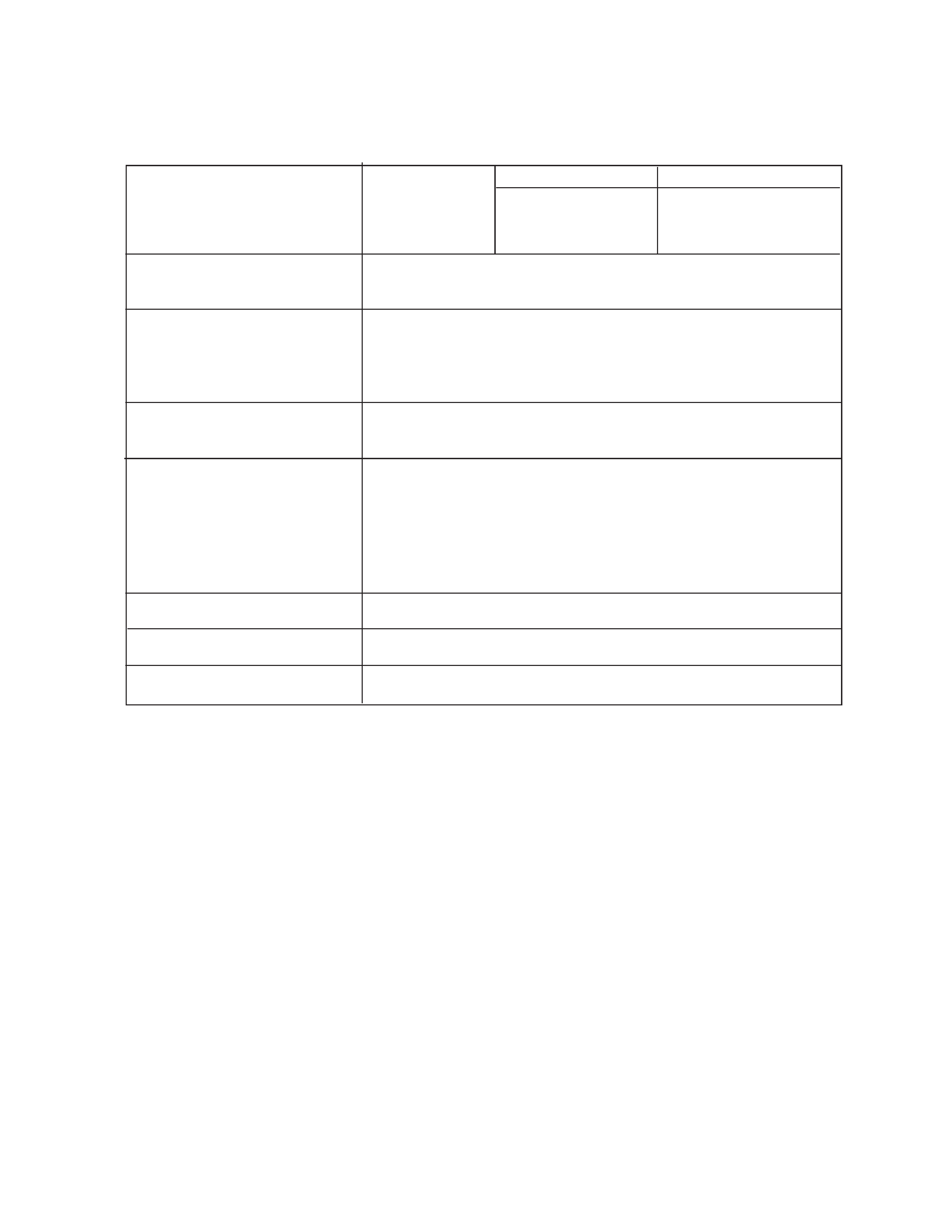
2. SPECIFICATION
2-1.
QT-2000
120V
230V
Power consumption
In operation
Max.: 0.7A
0.4A
Stand-by
Max.: 0.4A
0.3A
Mode SW OFF
Max.: 0.3A
0.2A
Memory
Standard:
384 KB
Max:
1MB
Memory protection
Back up battery
Lithium-Banadium battery VL3032/S6A
Back up period
30 days ( 25
°C )
Battery life
Replace every 5 years
Charging time
48 hours for full charge
Clock and calender
Accuracy
within
±30 sec./month ( 25 °C )
Auto calender
Effective 2099 A.D.
Environment
Operating temperature
0
°C ~ 40°C
Operating humidity
20% ~ 65%
Strorage temperature
-20
°C ~ 60°C
Storage humidity
10% ~ 80%
In the carton box : Storage temperature
-20
°C ~ 65°C
Storage humidity
10% ~ 80%
LCD display
LCD life
15,000 hours
Back light
Back light life
10,000 hours
Power prutection battery
No function
CAUTION
Danger of explosion if battery is incorrectly replaced.
Replace only with the same or equivalent type
recommended by the manufacturer.
Dispose of used batteries according
to the manufacture's instructions.
VORSICHT !
Explosionsgefahr bei unsachgemäßem Austausch der Batterie.
Ersatz nur durch denselben oder einen vom
Hersteller empfohlenen gleichwertigen Typ.
Entsorgung gebrauchter Batterien nach
Angaben des Herstellers.
ADVARSEL !
Lithiumbatteri - Eksplosionsfare ved fejlagtig hándtering.
Udskiftning má kun ske med batteri
af samme fabrikat og type.
Levér det brugte batteri tilbage til leverandØren.