R
JY-10B (NTSC)
(KX-513)
(without price)
SEPT. 1997
TUNING
POWER
UHF
VHF
13
1
30
40 50
62
CH
CH
2 3
4681012
VHF
UHF
DC
IN
6V
EAR
EXT ANT

CONTENTS
Page
SPECIFICATIONS ..................................................................................... 1
BLOCK DIAGRAM .................................................................................... 2
PRINTED CIRCUIT BOARDS ................................................................... 3
PARTS LIST .............................................................................................. 5
EXPLODED VIEW ..................................................................................... 9
SCHEMATIC DIAGRAMS ....................................................................... 10
WAVEFORMS ......................................................................................... 12
-- 1 --
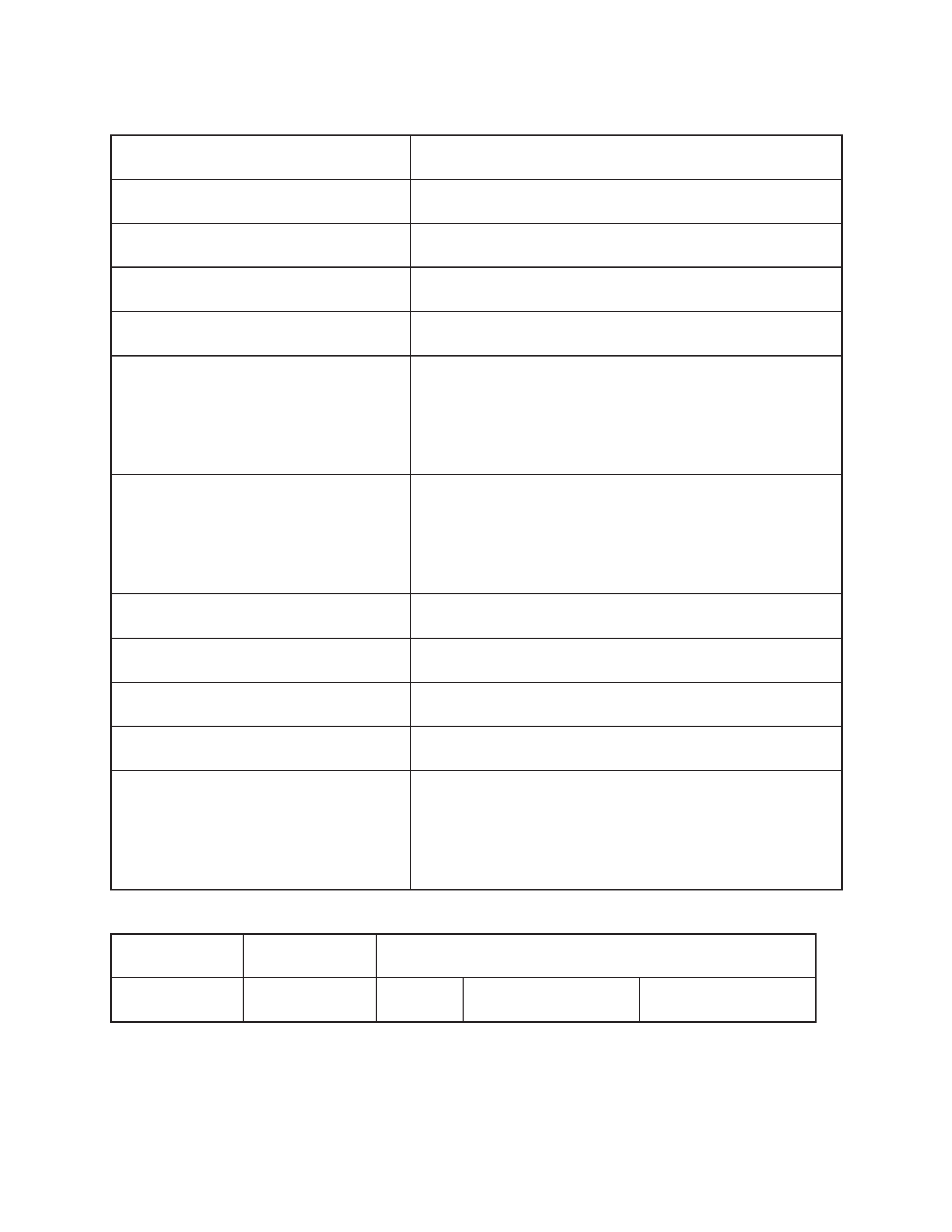
Item
Specification
1. Power voltage
DC 6.0 V
2. Power consumption
Approx. 3.5 W
3. Current consumption
Approx. 580 mA
4. Battery life (with alkaline batteries)
Approx. 4 hours
Batteries
: 4
× LR6 (D) size batteries
5. Power supply
Car adaptor : CA-K65
AC adaptor : AD-K64
Earphone jack
: 3.5 ø mini
6. Connection terminals
External power jack
: 6.0 V DC IN
External antenna jack
: 3.5 ø mini
7. Screen size
2.3 inches
8. No. of picture element
39,600 (360
× 110) dots
9. Dimensions
84 mm (H)
× 138 mm (W) × 51 mm (D)
10. Weight
230 g without batteries
AC adaptor
: AD-K64
11. Options
Car adaptor
: CA-K65
Antenna matching device : AS-35S
SPECIFICATIONS
Color System
TV System
Channel
NTSC
M / M
US
VHF: 2 ~ 13 ch
UHF: 14 ~ 69 ch
-- 2 --
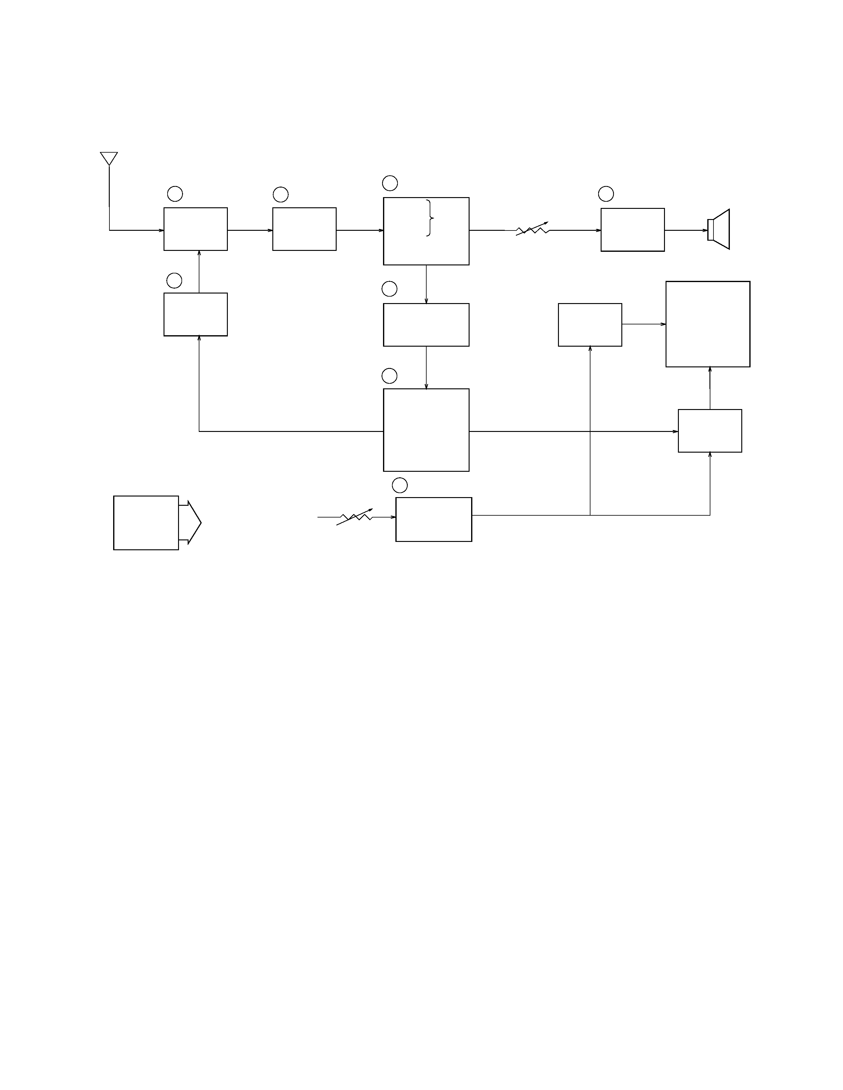
Antenna
1
TU200
2
Q200
3
IC200
7
Tuning
Voltage
Generator
VR600
Volume
Control
4
IC600
Speaker
IC300
IC700
Common
Driver
LCD
Segment
Driver
Chroma
Circuit
Osc.
Display
Control
A-D Converter
Auto-Tuning
Control
5
6
8
Q800 ~ Q803, Q805, Q806
VR800
Display
Voltage
Generator
Brightness
Control
VCC2 (3.95
± 0.02 V)
VCC7 (34.2 ~ 41.8 V)
VEE1 ( 6.03 ~ 7.37 V)
IC500
Power
Supply
Audio
Amp.
IF Amp.
Tuner
Video
Sound
Det.
FM
AFT Circuit
AGC Circuit
1
-- Color Tuner: TU200 TEPU5-02
Selects a desired radio wave and changes it to the video IF signal.
2
-- Video IF Amp.: Q200 2SC4238
Amplifies the video IF signal output from the tuner TU by 10 times (20 dB).
3
-- Video Det./Sound Det./FM Det./AFT/AGC: IC200 M51348FP
Eliminates the carrier wave in the video IF signal, and picks up the video signal and the sound IF signal.
Also, the sound signal is picked up from the sound IF signal by FM detection.
4
-- Audio Amp.: IC600 NJM2070M
Sound amplification.
5
-- Chroma Circuit: IC300 M52042FP
Generates the tricolor (red, green, and blue) from the video signal.
6
-- Osc./A-D Converter/Display Control/ Auto-Tuning Control : IC700 MSM6625-02 GSK-640F
Converts the color signal into a digital signal.
Also, generates the clock pulse for the display and controls the display.
7
-- Tuning Voltage Generator: IC500 MSC1169MS-K
Generates the tuning voltage with the tuning pulse (TU) output from 6.
8
-- Display Voltage Generator: Q800 ~ Q803 Q805 Q806 2SD1149-S,
2SD601A-R
×4, 2SB709A-R
Generates the display voltages V0 ~ V4 with VEE1 and VCC7 outputs from the power supply.
BLOCK DIAGRAM
-- 3 --
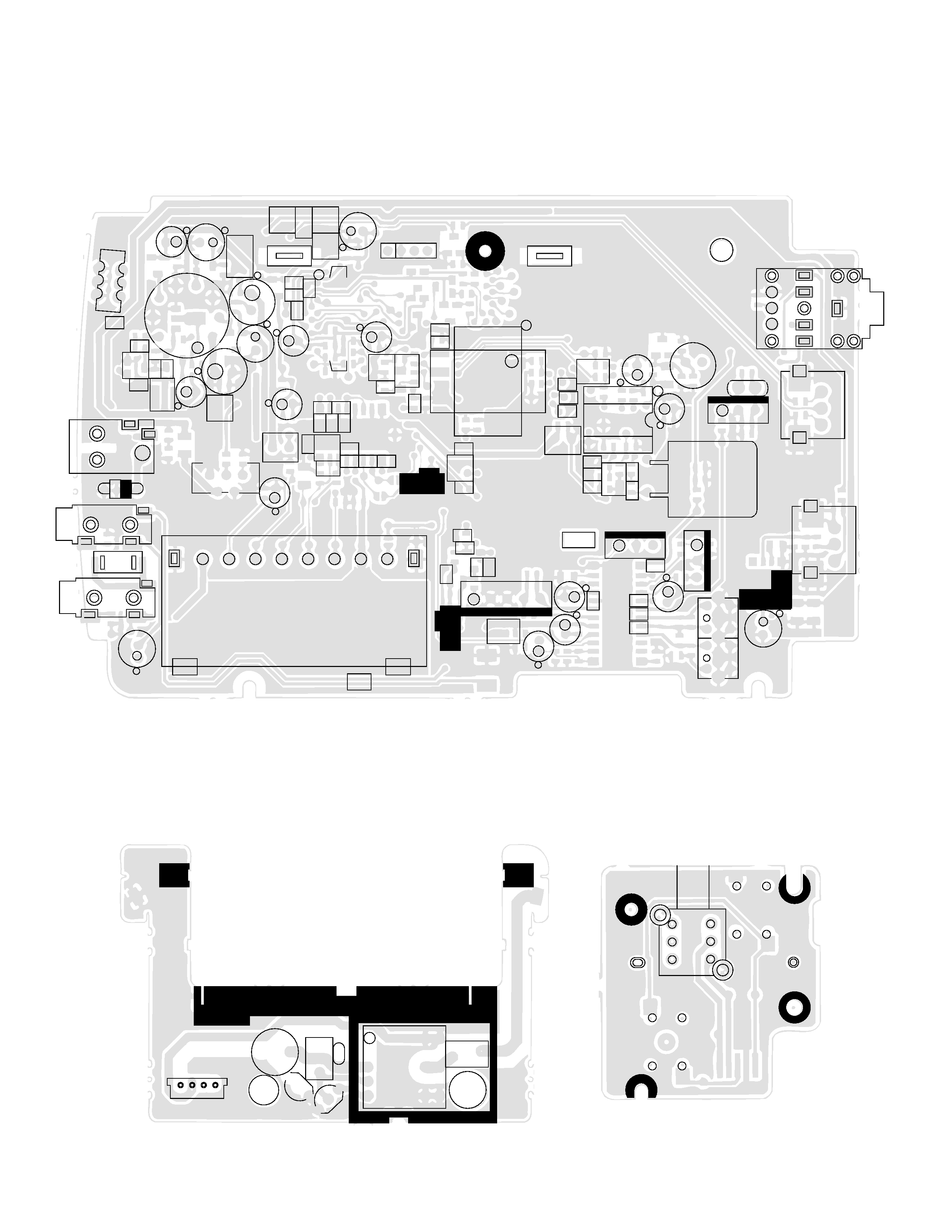
PRINTED CIRCUIT BOARDS
TOP VIEWS
Linear
Back Light
TU200
VR200
F200
D703
C205
C207
C210
C208
R222
R223
C259
R236
R251
R224
R700
L103
F210
C202
L102
CN710
C603
HP210
Q101
R170
C113
CN720
VR100
T100
C105
L101
C112
C110
SW110
C800
C806
CN700
HP110
Q805
C841
D805
D803
R121
R500
C137
R120
D110
R501
R502
R503
C530
R550
C550
R545
C545
C535R704
R738
R705
C750
C751
C782
C770
R745
L710
R105
C115
C100
C808
C700
D500
D707
VR700
JK100
JK600
D180
R201
R203
C236
C238
R205
C740
C741
C742
C345
R322
C346
R330
C350
VR301
IC300
VR300
C305
C309
C303
H300
F203
L202
VR800
VR600
JK250
HP100
IC700
C606
F220
T200
T201
JK200
1
1
1
L950
R950
T900
C927
C925
Q951
Q950
CN920
Switch
SW100