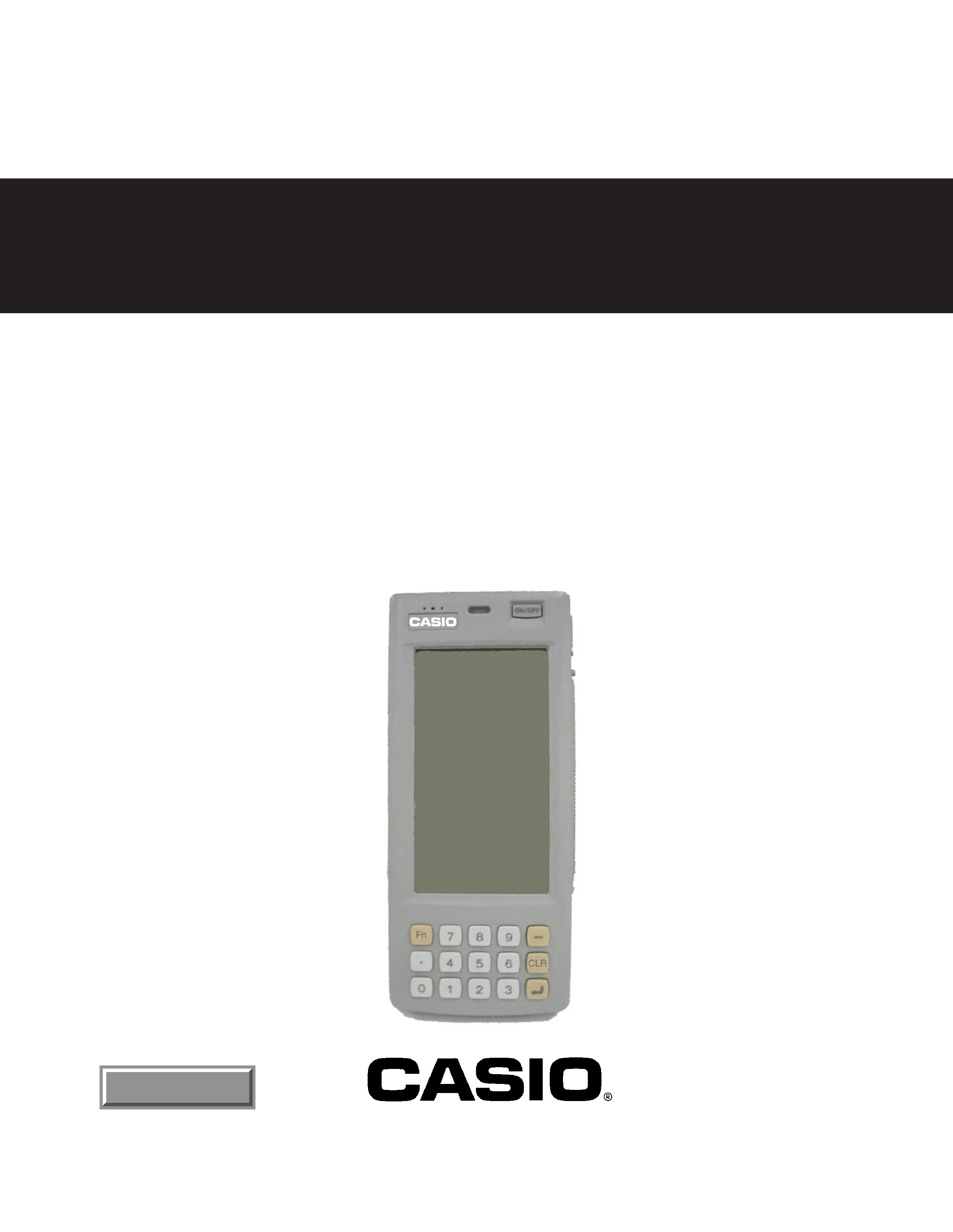
HANDY TERMINAL
IT-2000
(PX-704)
JAN 1998
SERVICE MANUAL
(without price)
INDEX

CONTENTS
1. SPECIFICATIONS ................................................................................................ 1
1.1 CPU ............................................................................................................. 1
1.2 Hardware ..................................................................................................... 1
1.3 Memory ....................................................................................................... 1
1.4 Touch Panel ................................................................................................ 1
1.5 Display ........................................................................................................ 1
1.6 Sound .......................................................................................................... 1
1.7 Key .............................................................................................................. 1
1.8 Interface ...................................................................................................... 1
1.9 PC card ....................................................................................................... 2
1.10 Power supply .............................................................................................. 2
1.11 Durability .................................................................................................... 2
2. OPTIONS .............................................................................................................. 3
3. INTERFACE PIN ASSIGNMENT .......................................................................... 5
3.1 8 Pin serial I/F ............................................................................................. 5
3.2 14 Pin serial I/F (RS-232C) ......................................................................... 5
3.3 Card I/F ........................................................................................................ 6
4. SYSTEM DIAGRAM ............................................................................................. 8
4.1 System diagram ......................................................................................... 8
4.2 Block diagram ............................................................................................ 9
4.3 PCB diagram ............................................................................................ 10
4.4 Power supply diagram ............................................................................. 11
5. CIRCUIT DESCRIPTION .................................................................................... 12
5.1 Memory ..................................................................................................... 12
5.2 KBC ........................................................................................................... 15
5.3 Communication ........................................................................................ 21
5.4 PC Card ..................................................................................................... 22
5.5 Power Supply ........................................................................................... 24
6. DISASSEMBLY .................................................................................................. 26
6.1 Removal of the main battery and the backup batteries ....................... 26
6.2 Removal of the battery pack cover ........................................................ 26
6.3 Removal of the Lower case block .......................................................... 26
6.4 Removal of SUB ass'y PCB .................................................................... 27
6.5 Disassembly of the Middle Case Block ................................................. 27
6.6 Disassembly of Upper Case Block ......................................................... 29
7. DIAGNOSTIC PROGRAM .................................................................................. 30
7.1 General ...................................................................................................... 30
7.2 Inspection Detail ...................................................................................... 32
7.3 Special tool ............................................................................................... 33
7.4 Diagnostic test ......................................................................................... 35
8. CIRCUIT DIAGRAMS ......................................................................................... 53
8.1 Curcuit diagram INDEX ........................................................................... 53
9. EXPLODED VIEW .............................................................................................. 75
10. PARTS LIST ........................................................................................................ 76

-- 1 --
1. SPECIFICATIONS
1.1 CPU
CPU: Intel 80486 GX (32 bit)
Clock: 25M Hz
1.2 Hardware
Configuration: IBM PC AT Architecture and dedicated hardware
1.3 Memory
Main memory:
4MB
16Mbit DRAM
× 2
File memory:
0MB
(for D10 Model)
4MB
32Mbit NAND Flash
× 1 (for D20 Model)
8MB
32Mbit NAND Flash
× 2 (for W30, D30P Model)
DOS & BIOS Memory:
1MB
8Mbit Flash E2PROM
× 1
MASK ROM:
8MB
64Mbit MASK ROM
× 1 (W30 Model only)
Video Memory:
512KB
4Mbit DRAM
× 1
HW Window Memory:
32KB
256Kbit SRAM
× 1
1.4 Touch Panel
Type:
Analog Type
Resolution:
192
× 384 dots
1.5 Display
LCD Type:
FSTN semi-transparent LCD
Resolution:
192
× 384 dots
Back light:
EL back light (with auto-off function)
Character type:
Alpha-numeric (ANK), user defined characters
Character size:
Normal size
12 dots: 6
× 12 dots
(Alpha-numeric)
16 dots: 8
× 16 dots
24 dots: 12
× 24 dots
Double size
12 dots: 12
× 12 dots
(Kanji)
16 dots: 16
× 16 dots
24 dots: 24
× 24 dots
Contrast:
VGA mode
4 gradation (Internal control 16 gradation)
HW Window
2 gradation
1.6 Sound
Sound source:
Buzzer
Volume:
4 steps (Max/Mid/Min/Off)
1.7 Key
Numeral keys:
11 (Including decimal point)
Function keys:
4 ("", "Fn", "CLR", "Return")
1.8 Interface
[COM1]:
8 pin serial I/F
Purpose:
for connections of BCR, PC
Baud rate:
300 ~ 115,200 bps
Transfer type:
Start-stop synchronous transmission
I/F level:
SD(1)
less than 5.0 V
SD(0)
more than +5.0 V
RD(1)
less than +0.6 V
RD(0)
more than +2.4 V

-- 2 --
[COM2]:
14 pin serial I/F (RS-232C)
Purpose:
for dedicated peripheral devices only
Baud rate:
300 ~ 115,200 bps
Transfer type:
Start-stop synchronous transmission
I/F level:
SD(1)
less than 5.0 V
SD(0)
more than +5.0 V
RD(1)
less than +0.6 V
RD(0)
more than +2.4 V
Infrared (conforms to IrDA Ver. 1.0)
Purpose:
for data transfer to I/O box
Baud rate:
2,400 ~ 115,200 bps
Transfer type:
Start-stop synchronous transmission
Transfer distance: 60 cm
Infrared (conforms to IrDA Ver. 1.1)
Purpose:
for data transfer to I/O box
Baud rate:
0.576/1.152/4M bps
Transfer type:
Flame synchronous transmission
Transfer distance: 60 cm
1.9 PC card
Conforms to PCMCIA 2.1 standard
Supply voltage: 3.3 V/5 V
1.10 Power supply
Main Battery
Type:
Lithium ion battery pack NP-500
Operating duration: 8 hours (Calculate: Display = 1:10, 20
°C, Back light = off)
Sub batteries
Type:
Primary: Coin type lithium ion battery CR2032
Secondary: Rechargeable battery IVR2430
Backup duration:
2 weeks
1.11 Durability
File memory (NAND Flash):Erasing 500,000 times
Touch panel:
100,000 characters
Back light:
2,500 hours (Half life period)
-- 3 --
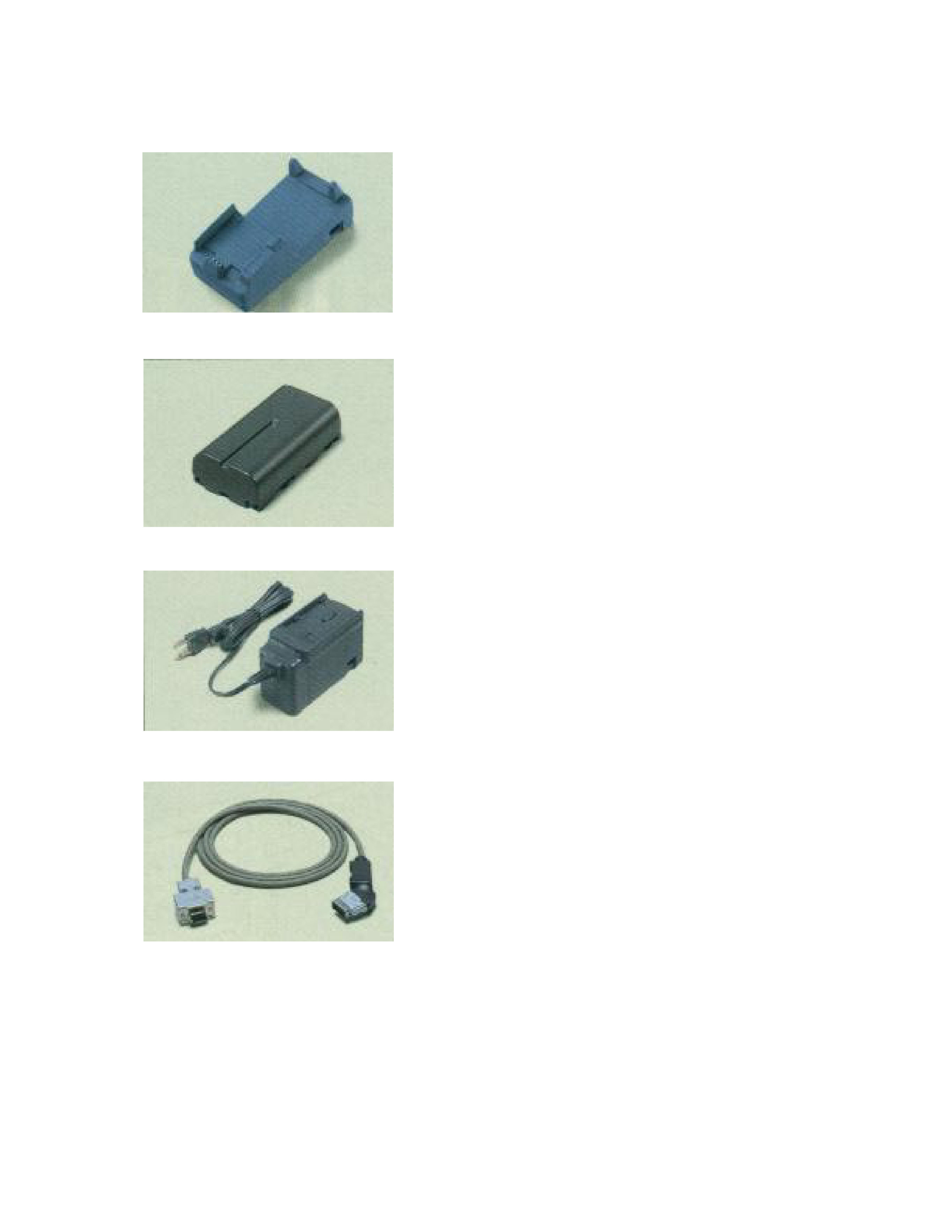
2. OPTIONS
I/O BOX
· IT-2060IO-E (Satellite I/O BOX)
· IT-2065IO-E (Master I/O BOX)
Battery pack
· DT-9023LI (Lithium ion battery pack)
Charger
· DT-9021CHG-E (for Lithum ion battery)
Cable
· DT-881RSC (MODEM cable between IT-2060/2065IO-
E/9-pin female and PC/25-pin male)
· DT-822RSC (Cross cable between IT-2060IO-E and
PC/25-pin male)
· DT-883RSC (Cross cable between IT-2060IO-E and
PC/25-pin female)
· DT-887AX (Cross cable between IT-2060IO-E and PC/
9-pin female)
· DT-888RSC (Modular cable between IT-2060/2065IO-E
and IT-2060/2065IO-E, 6-pin and 6-pin)
· DT-9689AX (RS-232C 9-pin cable between IT-2000 and
PC)
· SB-751HF (SCSI cable between IT-2065IO-E and PC
:Centro 50-pin full male)
· SB-752HH (SCSI cable between IT-2065IO-E and PC
:Centro 50-pin half male)
· SB-753HP (SCSI cable between IT-2065IO-E and PC
:Pin type half 50-pin male)