
R
(with price)
AUG. 1995
FV-600P (KX-0761P)
INDEX

CONTENTS
SPECIFICATIONS ......................................................................................... 2
SAFETY MEASURES .................................................................................... 3
ALARM DESCRIPTION ................................................................................. 3
BLOCK DIAGRAM ........................................................................................ 4
OPTICAL DIAGRAM ..................................................................................... 5
MONITOR SWITCHES .................................................................................. 5
TROUBLESHOOTING ................................................................................... 6
PARTS LIST FOR MAIN BLOCK .................................................................. 7
FOCUS ADJUSTMENT ................................................................................. 8
ADJUSTMENT MODE ................................................................................... 9
DISASSEMBLY ........................................................................................... 10
REPLACING THE FUSE ............................................................................. 18
REPLACING THE LAMP ............................................................................. 19
PRINTED CIRCUIT BOARDS ..................................................................... 21
EXPLODED VIEWS ..................................................................................... 25
ELECTRICAL PARTS LIST ......................................................................... 28
MECHANICAL PARTS LIST ....................................................................... 47
CPU PIN FUNCTION ................................................................................... 50
SCHEMATIC DIAGRAMS ........................................................................... 54
WAVEFORMS .............................................................................................. 58

-- 2 --
SPECIFICATIONS
Item
Specification
Receiving channels
CHINA:
CCIR:
AUST:
NZ:
UK, HK:
INDONESIA:
VHF: 1 ~ 12
UHF: 13 ~ 57
VHF: 2 ~ 12
UHF: 21 ~ 69
VHF: 0 ~ 11
UHF: 28 ~ 69
VHF: 1 ~ 11
UHF: 21 ~ 69
VHF:
-
UHF: 21 ~ 69
VHF: 1A ~ 11
UHF: 21 ~ 69
Power supply
220 ~ 240 V
Power consumption
120 W
Color system
PAL
NTSC (Only for Video in)
Input/Output terminals
External antenna:
Video in:
Audio in:
Earphone:
F connector
1.0 Vp-p, 75
308 m Vrms, 47 k
minimum
3.5 mm mini jack, 16
Screen size (Built-in screen)
10 inches
LCD panel
Size:
Type:
Driver:
No. of picture element:
2.4 inches
Transparent TN liquid crystal panel
a-Si TFT active matrix
245,960 (440 X 559) dots
Lens
Wide angle lens (F4.8, f=39.76 mm)
Lamp
80 W metal halide
Lamp life
Approx. 2,000 hours
Focus adjustment range
20 inches to 100 inches (Image size)
Speaker output
3 W
Operating temperature
0
° to 40°C (32° to 104°F)
Dimensions
28.8 (W) X 14.3 (D) X 41.0 (H) cm
11-5/16 (W) X 5-5/8 (D) X 16-1/8 (H) inches
Weight
6.2 kg (13.3 lbs.)

-- 3 --
SAFETY MEASURES
The power will be turned off automatically when FV-600 is in the following conditions.
1. Fan is stopped.
2. High temperature
(1) Thermistor detects high temperature.
(2) Bimetal detects high temperature.
3. Fan filter is not set properly.
4. Rear cover is not set properly.
ALARM DESCRIPTION
Power LED
Alarm LED
Beep
Description
Green On
Off
-
Power on
OK
Off
Off
-
Power off
Red On
Off
-
Power off by remote control
Green Blink
Off
-
Cooling off (Fan is working.)
Green On
Red Blink
Twice
High temperature warning
(Check the fan and fan filter.)
NG
Red Blink
Red Blink
Three times
1. Lamp is defective.
2. Fan is defective.
Red On
Red Blink
Once
1. Fan filter warning
(Check if the fun filter is set.)
2. Rear cover warning
(Check if the rear cover is set.)
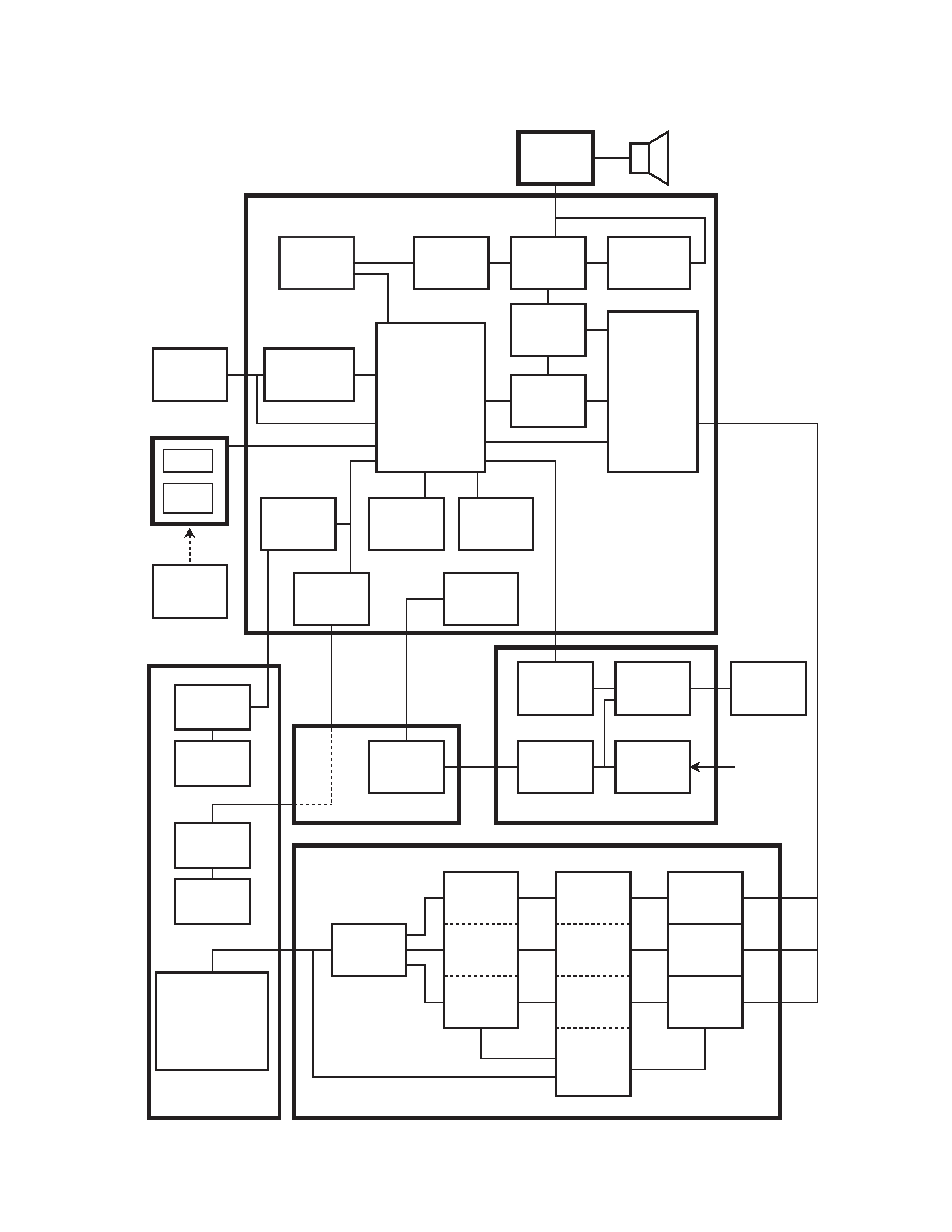
-- 4 --
TEKE7
Tuner
M51496
IF
BA7612
SW
TDA7056A
Audio
Amplifier
Filter
Low
Pass
Filter
µPD17068
CPU
Key
EEP-ROM
Focus
Drive
Circuit
Fan
Control
Circuit
Power
Supply
Circuit
D/A (B)
TA8783N
Chrominance
Circuit
Focus
Motor
Fan
Motor
Temperature
Detector
Thermistor
Photo
Sensor
Remote
Controller
Metal
Halide
Lamp
Lamp
Drive
Circuit
Control
Circuit
Input
Circuit
12 V
Power
Supply
440 X 559 dots
TFT LCD Module
IR3Y07
Polarity
Reverser
D/A (R)
µPC659
A/D (R)
Line
Memory
(R)
Line
Memory
(G)
Line
Memory
(B)
Controller
AC In
I / O
Circuit
Speaker
Relay
Linear PCB
RGB
Power Supply PCB
FPCB
A/D PCB
D/A (G)
µPC659
A/D (B)
µPC659
A/D (G)
MB4097
HG51B201
LED
RM PCB
JPCB
OPM Unit
Fan
Lens
BLOCK DIAGRAM