
file:///C|/Documents%20and%20Settings/bob/My%20Documents/manualdirectory.htm
This file was downloaded and provided FREE OF CHARGE
from the ManualDirectory community.
You can find many free to download Service Manuals & Schematics at
http://www.manualdirectory.co.uk
file:///C|/Documents%20and%20Settings/bob/My%20Documents/manualdirectory.htm01/04/2007 01:34:00

R
EV-510S (KX-609S)
EV-510L (KX-609L)
(without price)
SEPT. 1997
EV-510S
UHF
VHF
13
30
40
50
62
CH
1 2
3
4681012
CH
<
TUNNING
>
INDEX

CONTENTS
SPECIFICATIONS ......................................................................................... 1
BLOCK DIAGRAM ........................................................................................ 2
PRINTED CIRCUIT BOARDS ....................................................................... 3
EXPLODED VIEW ......................................................................................... 6
PARTS LIST .................................................................................................. 7
SCHEMATIC DIAGRAMS ........................................................................... 11
WAVEFORMS .............................................................................................. 14
-- 1 --
Item
Specification
1.
Reception channels
VHF: 1 ~ 12 ch
UHF: 13 ~ 69 ch
2.
Power voltage
DC 6.0 V
3.
Power consumption
Approx. 3.8 W
4.
Current consumption
Approx. 633 mA
Batteries
: 3 AA size batteries
5.
Power supply
Car adaptor : CA-K65
AC adaptor : AD-K65
Earphone jack
: 3.5ø mini
6.
Connection terminals
External power jack
: 6.0 V DC IN
External antenna jack
: 3.5ø mini
Audio / Video jack
: 3.5ø
7.
Screen size
2.5 inches
8.
No. of Picture element
61,380 (220
× 279) dots
9.
Dimensions
75 (W)
× 37 (D) × 121 (H) mm
10.
Weight
195 g excepting batteries
AC adaptor
: AD-K65, 64
11.
Options
Car adaptor
: CA-K65
RF connector
: CF-13
Antenna matching device : AS-35S
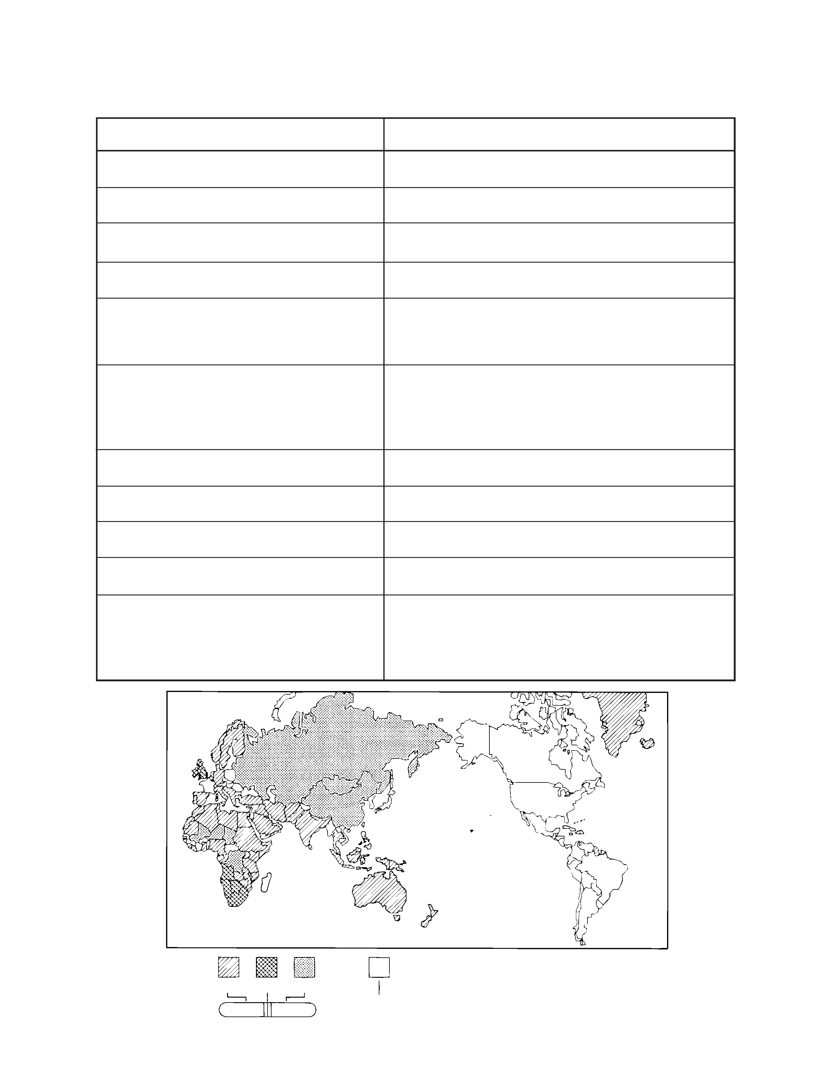
SPECIFICATIONS
Areas whose signals this TV cannot receive.
TU
V
-- 2 --
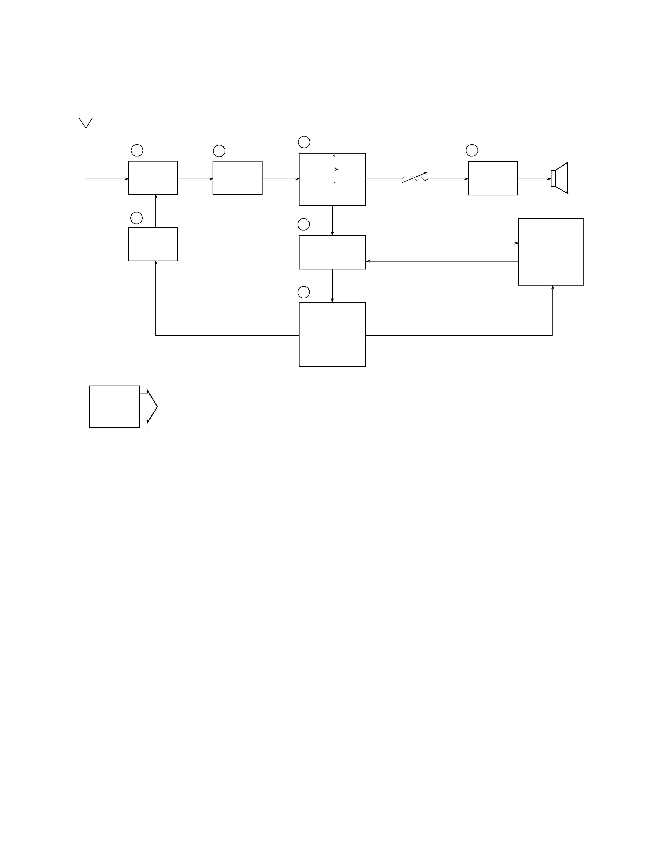
Antenna
1
TU200
2
Q200
3
IC200
7
Tuning
Voltage
Generator
VR600
Volume
Control
4
IC600
Speaker
IC300, IC400
IC700
LCD
Chroma
Circuit
Display
Control
Auto-Tuning
Control
5
6
VCC2 (4.5
± 0.02 V)
VCC7 (27.21 ~ 33.21 V)
VCC6 (10.26 ~ 12.54 V)
VEE1 (8.36 ~ 6.84 V)
VEE2 (20.36 ~ 16.66 V)
IC290
Power
Supply
Audio
Amp.
IF Amp.
Tuner
Video
Sound
FM
AFT Circuit
AGC Circuit
Det.
1
-- Color tuner: TU200 TEPU5-01
Selects a desired radio wave and changes it to the video IF signal.
2
-- Video IF amp.: Q200 2SC4238
Amplifies the video IF signal output from tuner TU200 by 10 times (20 dB).
3
-- Video det./Sound det./FM det./AFT/AGC: IC200 M51348FP
Eliminates the carrier wave in the video IF signal, and picks up the video signal and the sound IF signal.
Also, the sound signal is picked up from the sound IF signal by FM detection.
4
-- Audio amp.: IC600 NJM2070M
Sound amplification.
5
-- Chroma circuit: IC300 M51403FP/IC400 M51404AFP
Generates the tricolor (red, green, and blue) from the video signal.
6
-- Display control/Auto-tuning control: IC700 MSM6770CGS
Controls the display.
7
-- Tuning voltage generator: IC290 BA10358F
Generates the tuning voltage with the tuning pulse output from 6.
BLOCK DIAGRAM