(with price)
CTK-750
ELECTRONIC KEYBOARD
R
CTK-750

-- 14 --
CONTENTS
Specifications . . . . . . . . . . . . . . . . . . . . . . . . . . . . . . . . . . . . . . . . . . 1
Replacing the DSP (HG51A115A01FD) . . . . . . . . . . . . . . . . . . . . . 2
Block Diagram . . . . . . . . . . . . . . . . . . . . . . . . . . . . . . . . . . . . . . . . . 3
Circuit Description . . . . . . . . . . . . . . . . . . . . . . . . . . . . . . . . . . . . . 4
Wiring Diagram . . . . . . . . . . . . . . . . . . . . . . . . . . . . . . . . . . . . . . . 13
Major Waveforms . . . . . . . . . . . . . . . . . . . . . . . . . . . . . . . . . . . . . . 14
PCB View and Major Check Points . . . . . . . . . . . . . . . . . . . . . . . 16
Schematic Diagrams . . . . . . . . . . . . . . . . . . . . . . . . . . . . . . . . . . 17
Exploded View . . . . . . . . . . . . . . . . . . . . . . . . . . . . . . . . . . . . . . . . 20
IC and Transistor Lead Identification . . . . . . . . . . . . . . . . . . . . . 21
Parts List . . . . . . . . . . . . . . . . . . . . . . . . . . . . . . . . . . . . . . . . . . . 23

-- 1 --
General
Number of Keys:
61
Polyphonic:
32-note
Preset Tones:
128
Tone Expander: Layer, Split
Keyboard Controls:
Touch Response: On/Off
Touch Sensitivity: Light/Middle/Heavy
Key Transpose:
Range from F# to F by a half-note increment
Auto-Rhythms:
128
Tempo Control: 40 to 255
Auto-Accompaniment:
CASIO Chord/Fingered/Full-Range Chord
Controller: Variation, Fill-In, Intro/Ending
Magical Preset Variations:
128; BREAK BEAT
16
MELODYCOMP
8
SHADOW DRUM
4
FREE SESSION
32
TONE STACK
40
KEY SPLIT
12
HYPERACTIVE
16
Digital Effects:
16;
Reverb-1, Reverb-2, Reverb-3, Chorus, Tremplp, Phase Shifter,
Organ SP, Enhancer, Flanger, EQ Loudness, Delay-1, Delay-2,
Analog Delay, Tap Delay, Chorus Reverb, Tremolo Reverb
Sound/Control Pads:
6
Pad Variations:
32;
Phrases: 10, Drums: 10, SE/Percussion: 10, Controller: 2
Song Memories:
2;
Tracks: 6
System: Real-time recording
Memory Capacity: Approx. 5,800 notes
Registration Memories:
10
Registration Items:
Tone Number, Rhythm Number, Tempo, Accompaniment Mode,
Accompaniment Volume, Effects, Layer On/Off, Split On/Off,
Pad Variation, Assignable Jack, Auto-Accompaniment On/Off,
Auto-Accompaniment Controller, MIDI (Channel On/Off, GM On/Off,
Local Control On/Off, Bend Range)
Tuning Control:
440Hz
± 100 cents
Terminals:
Headphone Jack [Output Impedance: 100
, Output Voltage: 1.7 V(rms)
MAX], Assignable Jack, MIDI Jacks (IN, OUT), AC Adaptor Jack (12V)
Built-In Speakers:
12 cm dia. 1.1W Input Rating: 2 pcs.
Power Source:
2-way AC or DC source
AC: AC adaptor AD-12
DC: 6 D size dry batteries
Battery life: Approx. 5 hours by manganese batteries R20P(SUM-1)
Approx. 5 hours by alkaline batteries LR20(AM1)
Auto Power Off:
Approximately 6 minutes after the last operation
Power Consumption:
18 W
Dimentions:
141 x 968 x 411 mm (HWD)
(5-11/16 x 38-1/16 x 16-5/16 inches) (HWD)
Weight:
7.0 kg (15.5 lbs) excluding batteries
Standard Accessory:
Music stand
SPECIFICATIONS
-- 2 --
Electrical
Current Drain with 12V DC:
No Sound Output
390 mA
± 20%
Maximum Volume
1700 mA
± 20%
with white keys D2 to D3 pressed in Synth-Bass-2 tone
and in Latin Fusion rhythm at initial setup tempo
Volume; maximum, Touch: maximum
Line Output Level (Vrms with 47 K
load each cannel):
with key D4 pressed in FSynth-Bass-2 tone on L-ch
850 mV
± 20%
with key G4 pressed in FSynth-Bass-2 tone on R-ch
800 mV
± 20%
Phone Output Level (Vrms with 8
load each channel):
with key D4 pressed in FSynth-Bass-2 tone on L-ch
280 mV
± 20%
with key G4 pressed in FSynth-Bass-2 tone on R-ch
260 mV
± 20%
Speaker Input Level:
with key D4 pressed in FSynth-Bass-2 tone on L-ch
5200 mV
± 20%
with key G4 pressed in FSynth-Bass-2 tone on R-ch
5600 mV
± 20%
Minimum Operating Voltage:
5.5 V
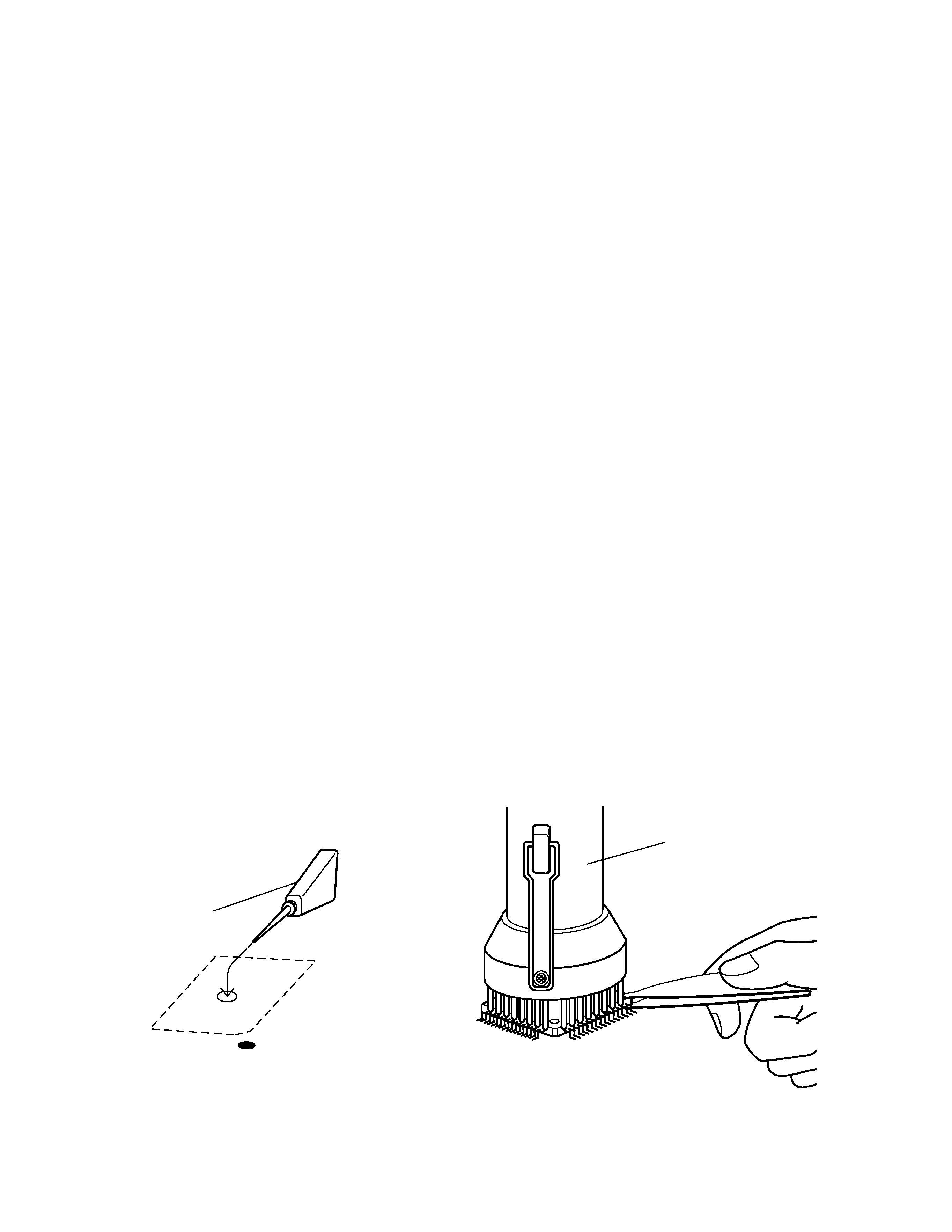
REPLACING THE DSP (HG51A115A01FD)
Note: To increase productivity ,the DSP HG51A115A01FD is sticked on the main PCB with a double-side
adhesive tape, then its leads are soldered.
Remove the DSP according to the following procedures.
1. Prepare isopropyl alcohol and a flat IC desoldering machine (Spot Heater HS-600).
2. Apply plenty of the alcohol to the adhesive tape from the reverse side of the main PCB. (Fig. 1)
There is a hole on the PCB just under the LSI, and the adhesive tape can be seen through the hole.
3. Leave it more than one minute so that the alcohol weaken adhesive power fully.
4. Using a proper size of nozzle, apply heat to leads of the LSI with the desoldering machine.
5. Grasp the LSI with tweezers, and using gentle force vibrate the tweezers to feel melting solder. (Fig.2)
6. Remove the LSI after meltingsolder at every leads wholly.
Alcohl
Spot Heater HS-600
Fig.2
Fig.1
HG51A115A
LSI-S
-- 3 --
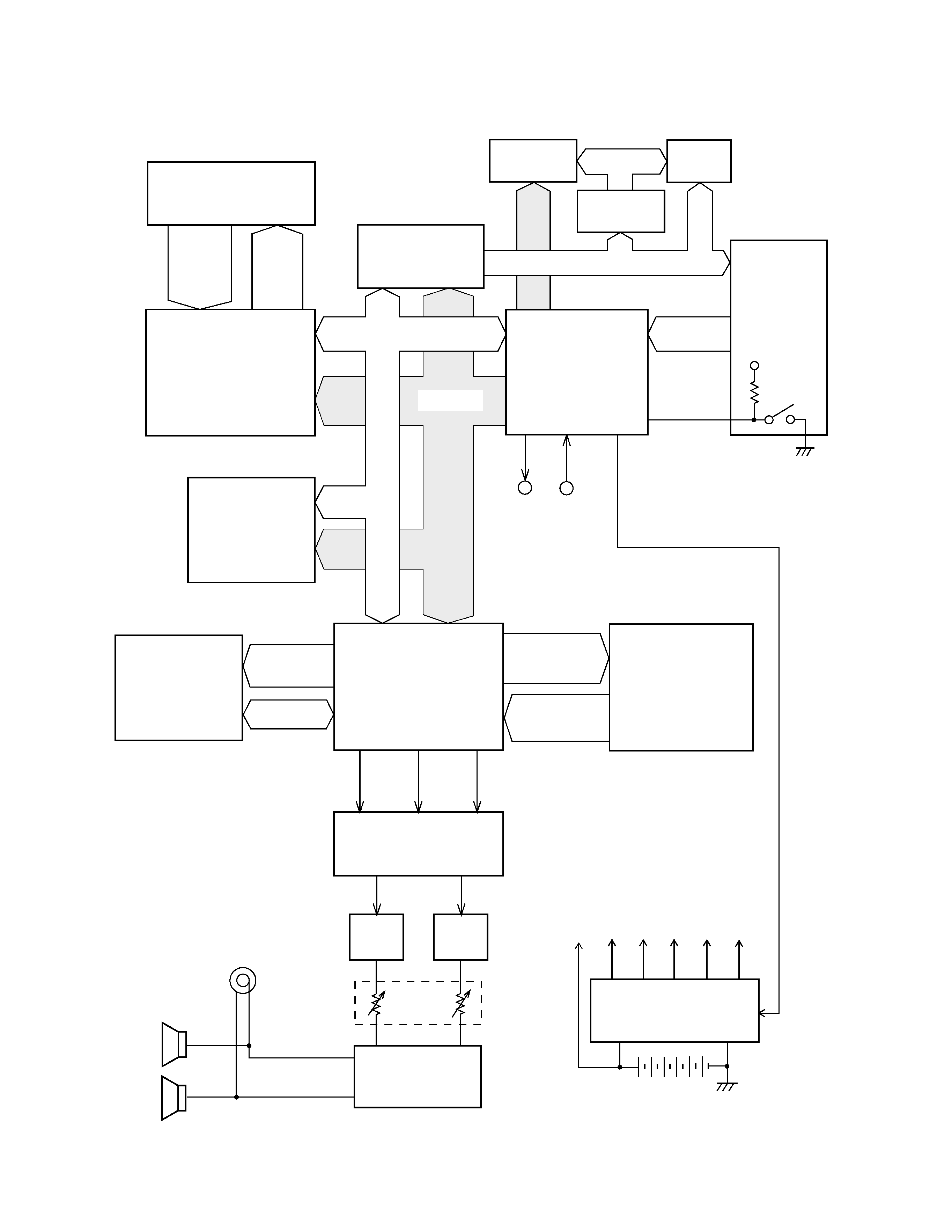
BLOCK DIAGRAM
KC0 ~
KC7
SI0 ~ SI7
FI0 ~ FI7
Key Touch LSI
HG52E35P
Working Strage
RAM (256K-bit)
HM62256ALP-10
Working Strage
RAM (256K-bit)
HM62256ALP-10
7-Segment
LED
LO0 ~ LO4
LED driver
BA612
LD0 ~ LD7
KO0 ~ KO7
Buttons
KI1 ~ KI7
VDD
Power Switch
MIDI
IN
OUT
EA0 ~ EA14
ED0 ~ ED7
DSP
HG51A115A01FD
RA0 ~ RA19
RD0 ~ RD15
Sound Source ROM
(16M-bit)
TC5316200CP-C081
WCK1
SLOP
BCK
D/A Converter
UPD6376CX
Filter
Filter
Main
Volume
Power Amplifier
LA4620
Gate Array
UPD65005C-578
CPU
HD6433298A18P
Keyboard
A0 ~ A15
POWER
Power Supply Circuit
Q1 ~ Q7
VCC
AVDD
VDD
LVDD
DVDD
VD
APO
Effect RAM
(256K-bit)
HM62256ALP-10
D0~D7
Speakers
Output
A0 ~ A14
A0 ~ A3
A0 ~ A2
LEDs