ELECTRIONIC KEYBOARD
CTK-50
CTK-50
(without price)
INDEX

-- 2 --
ELECTRICAL
Nominal
Limit
Current drain with 9V DC:
No sound output
50 mA
50 mA
± 30%
Maximum volume
515 mA
515 mA
± 30%
with keys C1, D1, E1 and F1 pressed
in Car-Horn tone, Volume; Maximum
Sound Pressure Level at 10 cm away from speaker:
108 dB
108
± 10 dB
with key C4 pressed in Car-Horn tone
Volume; Maximum
Minimum operating voltage:
5.8 V
6.0 V
GENERAL
Number of keys:
49
Polyphonic:
8-note
Preset tones:
100
Auto-rhythms:
100
Auto-accompaniment:
CASIO Chord/Fingered
Demonstration tune:
Classical Medley
Built-in speakers:
10 cm dia. 2.0W Input Rating: 1 pc.
Terminal:
AC Adapter Jack (DC 9 V)
Power source:
2-way AC or DC source
AC: AC adapter
DC: 6 AA size dry batteries
Power consumption:
6.0 W
Dimensions:
79 x 766 x 269 mm (HWD)
(3-1/8 x 33 x 10-5/8 inches) (HWD)
Weight:
2.8 kg (6.2 lbs) excluding batteries
SPECIFICATIONS
CONTENTS
Specification .............................................................................. 2
Block Diagram ........................................................................... 3
Circuit Description ..................................................................... 4
Troubleshooting ........................................................................ 7
Major Waveforms ...................................................................... 8
Schematic Diagrams ................................................................. 9
PCB View ................................................................................ 11
Exploded View ........................................................................ 12
Parts List ................................................................................. 13
--
3
--
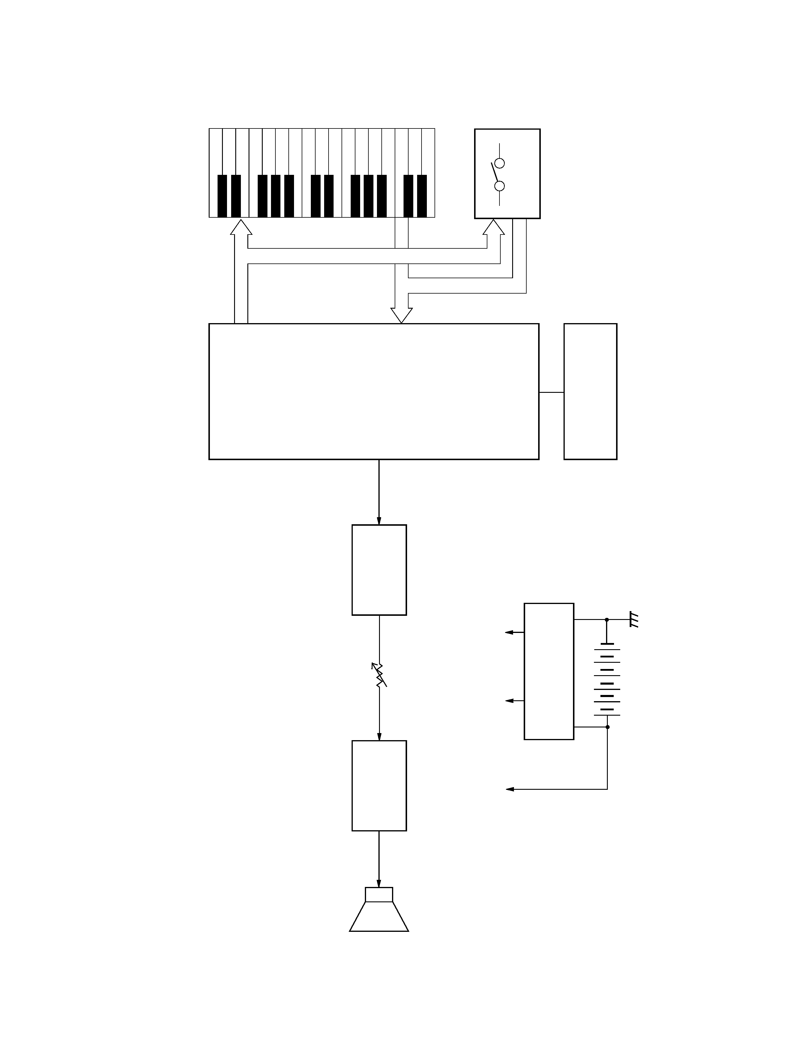
BLOCK DIAGRAM
KO0~KO9
KI0~KI7
Keyboard
Switches
Oscillator
Q301, X301
VDD +5 V
Power supply circuit
Q101, Q102, D102
VC +9 V
Amplifier
A4598
IC101
Speaker
Filter
Q201
CPU
MSM6387-13
LSI201
Main Volume
AVDD +4.8 V
-- 4 --
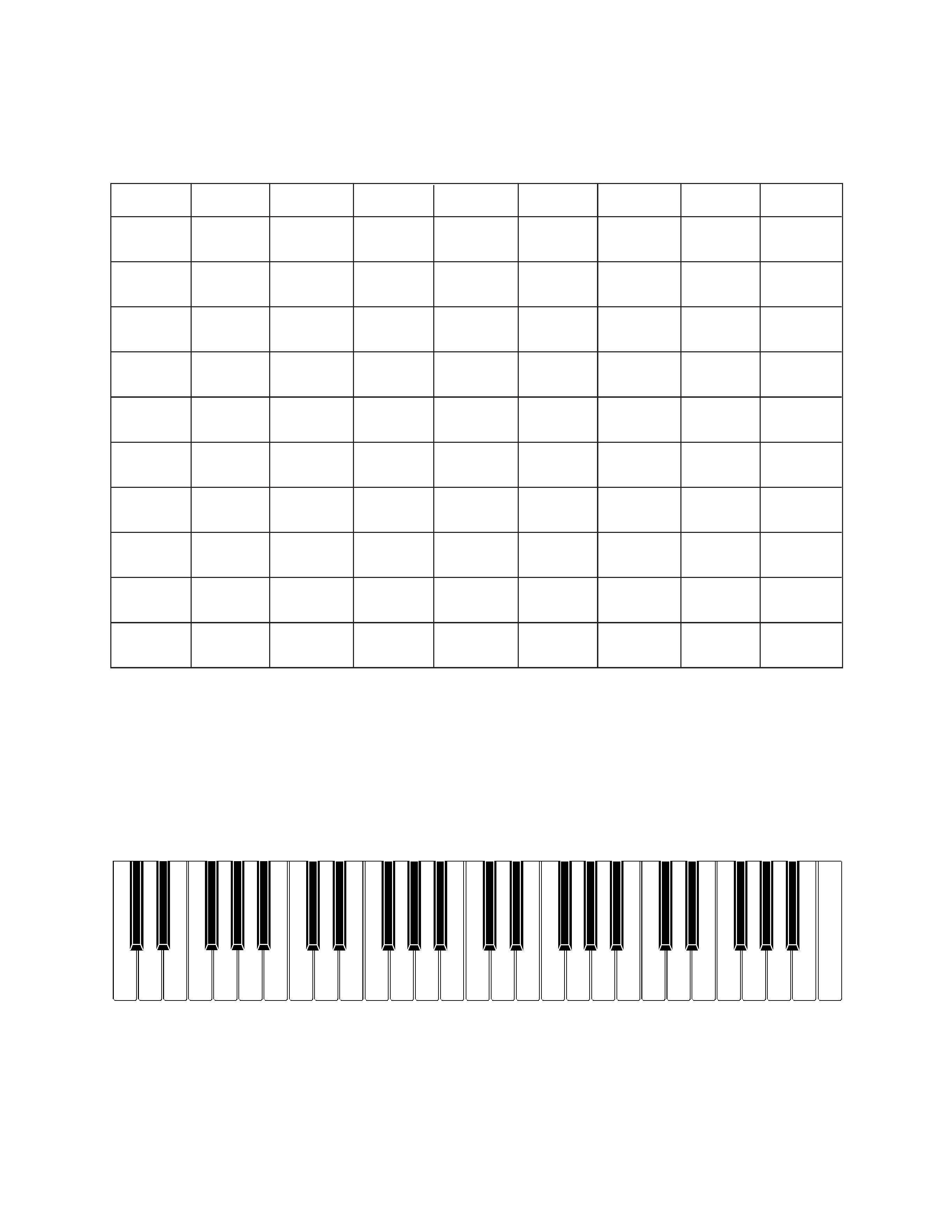
NOMENCLATURE OF KEYS
CIRCUIT DESCRIPTION
KEY AND SWITCH MATRIX
F#3 G#3 A#3
C#4 D#4
F#4 G#4 A#4
C#5 D#5
F#5 G#5 A#5
F3
G3
A3
B3
C4
D4
E4
F4
G4
A4
B4
C5
D5
E5
F5
G5
A5
B5
C6
D#3
C#3
A#2
G#2
F#2
D#2
C#2
C2
D2
E2
F2
G2
A2
B2
C3
D3
E3
KI0
KI1
KI2
KI3
KI4
KI5
KI6
KI7
KO0
0
1
C2
C#2
D2
D#2
E2
F2
(KC1)
KO1
2
3
F#2
G2
G#2
A2
A#2
B2
(KC2)
KO2
4
5
C3
C#3
D3
D#3
E3
F3
(KC3)
KO3
6
7
F#3
G3
G#3
A3
A#3
B3
(KC4)
KO4
8
9
C4
C#4
D4
D#4
E4
F4
(KC5)
KO5
Tone
Rhythm
F#4
G4
G#4
A4
A#4
B4
(KC6)
KO6
Tempo
Tempo
C5
C#5
D5
D#5
E5
F5
(KC7)
Up
Down
KO7
Start/
Fill-In
F#5
G5
G#5
A5
A#5
B5
(KC8)
Stop
KO8
Demo
C6
(KC9)
KO9
Normal
Fingered
CASIO
Chord
-- 5 --
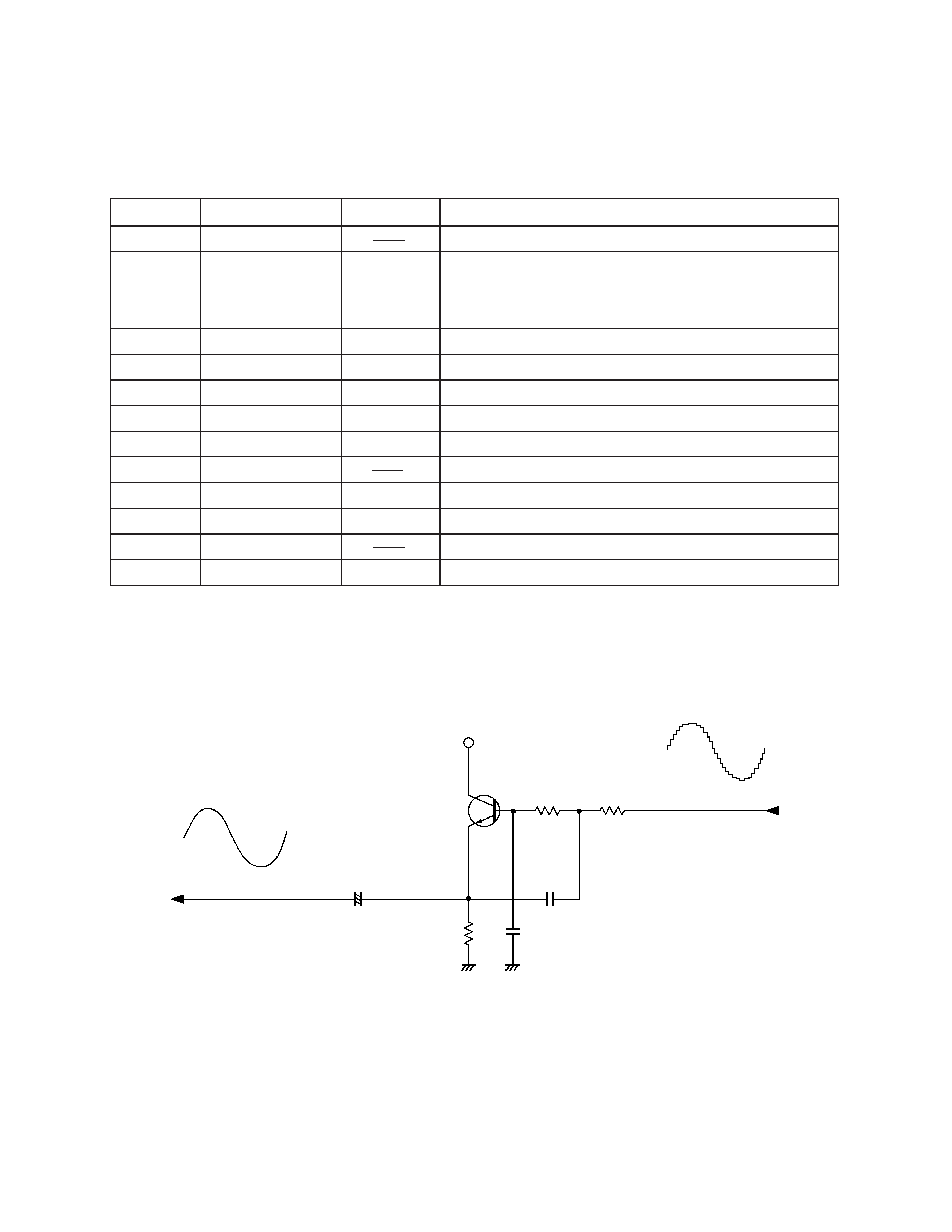
Pin No.
Terminal
In/ Out
Function
1, 2
TEST1, TEST2
Not used. Connected to ground.
Power ON reset terminal. When the power switch is
3
RESET
In
turned on, the terminal receives a low level signal and
the internal circuits of the LSI are initialized.
4
AVDD
In
+5 V sorce for the built-in DAC
5
OUT
Out
Sound waveform output
6
AGND
In
Ground (0 V) source for the built-in DAC
7
GND
In
Ground (0 V) source
8
COSI
In
21.725 MHz clock pulse input
9
COSO
Not used.
10
VDD
In
+5 V source
11 ~ 18
KI0 ~ KI7
In
Input terminals from keys and switches
19, 20
KO11, KO10
Not used.
21 ~ 30
KO9 ~ KO0
Out
Key and switch scan signal outputs
CPU (LSI201: MSM6387-13)
The CPU contains a sound data ROM and a DAC (Digital to Analog Convertor), and it provides a sound
waveform in accordance with the pressed key and the selected tone.
The following table shows the pin functions of LSI201.
FILTER BLOCK
Since the sound signal from the CPU is a stepped waveform, the filter block is added to smooth the
waveform.
AVDD
C203
Q201
2SC1740SQ
R202
C202
AG
AG
R204
R203
C201
To main volume
From CPU