
SERVICE
MANUAL
REVISION 0
COPYRIGHT © 1996 CANON INC.
CANON GP215/200 REV.0 JULY 1996 PRINTED IN JAPAN (IMPRIME AU JAPON)
JULY 1996
FY8-13EE-000

COPYRIGHT © 1996 CANON INC.
Printed in Japan
Imprimé au Japon
Use of this manual should be
strictly supervised to avoid
disclosure
of
confidential
information.
COPYRIGHT © 1996 CANON INC.
CANON GP215/200 REV.0 JULY 1996 PRINTED IN JAPAN (IMPRIME AU JAPON)
IMPORTANT
THE INFORMATION CONTAINED HEREIN IS PUBLISHED BY CANON, INC., JAPAN, AND IS
FOR REFERENCE USE ONLY. SPECIFICATIONS AND OTHER INFORMATION CONTAINED
HEREIN MAY VARY SLIGHTLY FROM ACTUAL MACHINE VALUES OR THOSE FOUND IN
ADVERTISING AND OTHER PRINTED MATTER.
ANY QUESTIONS REGARDING INFORMATION CONTAINED HEREIN SHOULD BE DIRECTED
TO THE COPIER SERVICE DEPARTMENT OF THE SALES COMPANY.
Prepared by
OFFICE IMAGING PRODUCTS TECHNICAL SUPPORT DEPARTMENT 1
OFFICE IMAGING PRODUCTS TECHNICAL SUPPORT DIVISION
CANON INC.
30-2, Shimomaruko 3-chome, Ohta-ku, Tokyo 146 Japan

This Service Manual provides basic facts and figures needed to service the GP215/GP200 in the field.
The GP215/GP200 is designed to accommodate fax and printer functions in addition to copier functions,
and separate service manuals are available for each function; refer to the appropriate service manual as
necessary.
This Service Manual is organized as follows:
CHAPTER 1, "General Introduction," shows the GP215/GP200's features, specifications, and step-by-
step instructions on how to operate the copier.
CHAPTER 2, "Copying Processes," shows how the GP215/GP200 generates copies while discussing
each of the steps involved.
CHAPTER 3, "Operations and Timing," explains the GP215/GP200's mechanical system by function
and principles behind its electrical systems in relation to timing of each operation.
CHAPTER 4, "Mechanical System," explains how to disassemble/assemble and adjust the
GP215/GP200.
CHAPTER 5, "Installation," provides points to note when selecting the site of installation and instruc-
tions on how to install the GP215/GP200.
CHAPTER 6, "Maintenance and Inspection," provides tables of periodically replaced parts and con-
sumables/durables as well as a scheduled servicing chart.
APPENDIX contains a general timing chart, general circuit diagrams, and PCB diagrams.
This Service Manual is accompanied by the Service Handbook, which contains information on how to
maintain and inspect the GP215/GP200 through adjustment and troubleshooting work.
Information found in this manual may be updated from time to time for product improvement, and major
updates are communicated in the form of Service Information bulletins.
All service persons are expected to be thoroughly familiar with the contents of this Service Manual, the
Service Handbook, and Service Information bulletins and be ready to respond to the needs of the user
promptly.
i
COPYRIGHT © 1996 CANON INC.
CANON GP215/200 REV.0 JULY 1996 PRINTED IN JAPAN (IMPRIME AU JAPON)
INTRODUCTION
s
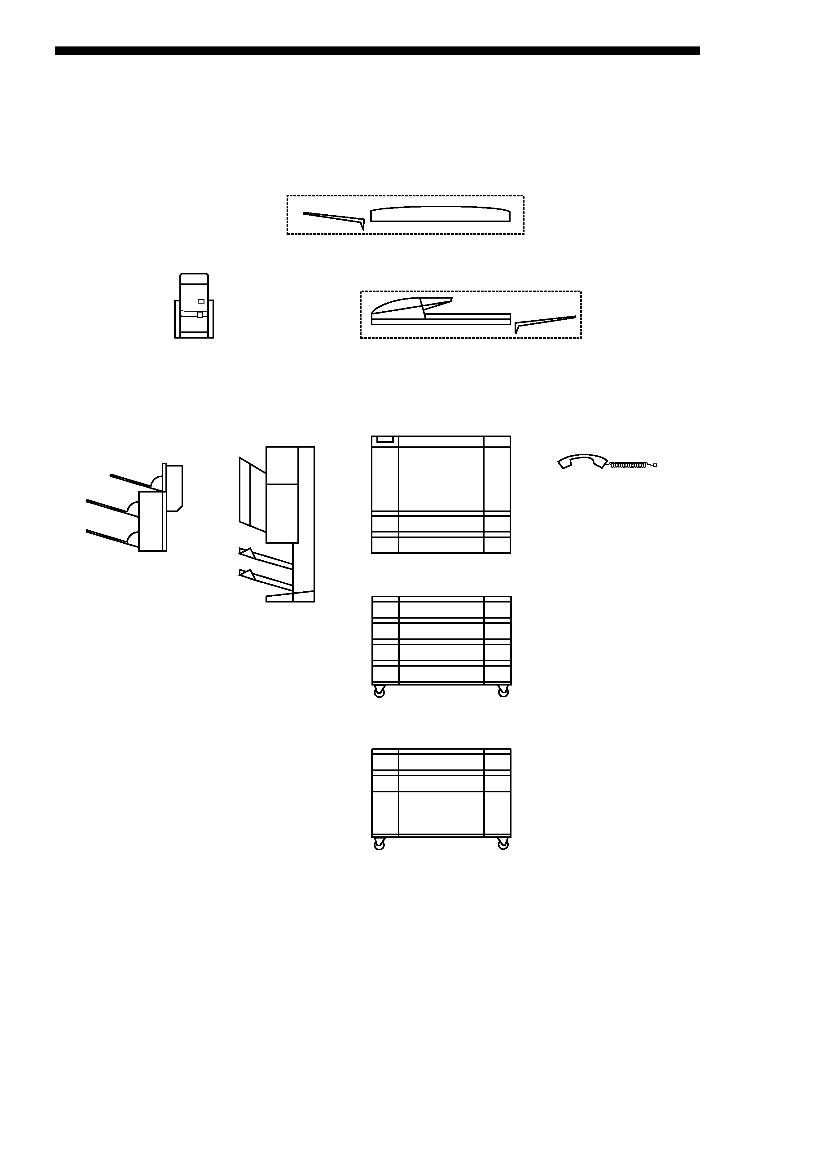
s System Configuration
The GP200/GP215 Series machine may be configured as follows:
ADF-F1 (comes standard with some models)
RDF-G1 (comes standard with some models)
Projector
GP215F (w/ fax function)
GP215 (w/o fax function)
GP200F (w/ fax function, w/o duplexing function)
GP200 (w/o fax function, w/o duplexing function)
Cassette Feeding Unit-L1
Cassette Feeding Unit-M1
Handset
Multi-Output Tray-C1 Multi-Output Tray-B2
COPYRIGHT © 1996 CANON INC.
CANON GP215/200 REV.0 JULY 1996 PRINTED IN JAPAN (IMPRIME AU JAPON)
ii

CONTENTS
iii
COPYRIGHT © 1996 CANON INC.
CANON GP215/200 REV.0 JULY 1996 PRINTED IN JAPAN (IMPRIME AU JAPON)
CHAPTER 1 GENERAL DESCRIPTION
I.
FEATURES ..............................................1-1
II.
SPECIFICATIONS ...................................1-2
III.
NAMES OF PARTS .................................1-8
A.
External View ...................................1-8
B.
Cross Section .................................1-10
C.
Arrangement of Extension Boards ....1-12
IV.
OPERATION ..........................................1-13
A.
Turning On the Power Switches .....1-13
B.
Control Panel..................................1-14
C.
Basic Operation ..............................1-16
D.
Extension Mode..............................1-19
E.
Costom Common Settings .............1-25
V.
ROUTINE WORK BY THE USER .........1-29
VI.
SAFETY.................................................1-30
A.
Laser Beams ..................................1-30
B.
Safety of Toner ...............................1-31
CHAPTER 2 COPYING PROCESS
I.
IMAGE FORMATION ...............................2-1
A.
Outline ..............................................2-1
B.
Latent Image Formation Block .........2-2
C.
Pre-Exposure (step 1) ......................2-3
D.
Primary Charging (step 2) ................2-3
E.
Laser Exposure (step 3) ...................2-4
F.
Development (step 4) .......................2-4
G.
Transfer (step 5) ...............................2-5
H.
Separation (step 6)...........................2-6
I.
Fixing (step 7)...................................2-7
J.
Dram Cleaning .................................2-7
II.
AUXILIARY PROCESS............................2-8
CHAPTER 3 OPERATIONS AND TIMING
I.
BASIC OPERATION ................................3-1
A.
Functional Construction....................3-1
B.
Outline of the Electrical Circuitry......3-2
C.
Inputs to the Major PCBs .................3-6
D.
Main Motor Control PCB ................3-16
II.
ORIGINAL EXPOSURE SYSTEM.........3-20
A.
Outline ............................................3-20
B.
Varying the Reproduction Ratio .....3-22
C.
Sequence of Operations
(original exposure system) .............3-22
D.
Scanner Motor ................................3-23
E.
Controlling the Scanning Lamp ......3-24
F.
Identifying the Size of Originals......3-26
III.
IMAGE PROCESSING ..........................3-29
A.
Outline ............................................3-29
B.
Analog Image Processing ..............3-31
C.
Digital Image Processing................3-33
IV.
LASER EXPOSURE SYSTEM ..............3-51
A.
Laser Processing Assembly ...........3-51
B.
Generating the BD Signal ..............3-53
C.
Laser Driver Circuit.........................3-54
D.
Controlling the Laser Scanner Motor ...3-56
V.
IMAGE FORMATION SYSTEM .............3-58
A.
High-Voltage Transformer Circuit ......3-58
B.
Controlling the
Primary Charging Roller Bias.........3-60
C.
Controlling the
Transfer Charging Roller Bias ........3-63
D.
Controlling the Developing Bias .....3-66
E.
Controlling the
Separation Static Eliminator Bias ...3-68
F.
Controlling the
Transfer Guide/Fixing Roller Bias ...3-69
G.
Developing Assembly/ Drum Cleaner ...3-70
H.
Primary Charging Roller
Cleaning Mechanism ......................3-73
I.
Detecing Errors on the
Composite Power Supply PCB.......3-74
VI.
PICK-UP/FEEDING SYSTEM ...............3-76
A.
Outline ............................................3-76
B.
Pick-Up from the Cassette .............3-79
C.
Non-Pick Up Operation (standby)....3-91
D.
Detecting the Level of Copy Paper ...3-93
E.
Detecting the Size of Copy Paper ...3-95
F.
Multifeeder ....................................3-100
G.
Controlling the
Registration Roller Clutch.............3-103
H.
Making Overlay Copies ................3-104
I.
Making Two-Sided Copies............3-106
J.
Lower Feeding Assembly .............3-108
K.
Fixing/Delivery Assembly .............3-118
L.
Delivery Assembly ........................3-127