SERVICE MANUAL
DA
TA
COMPACT DISC
STEREO SYSTEM
BASIC TAPE MECHANISM : 2ZM-1 R10NM
BASIC CD MECHANISM : TN-CCD1001-902M
XR-MS3
U,EZ
S/M Code No. 09-002-422-6R1
REVISION
· This Service Manual is the "Revision Publishing" and replaces "Simple Manual"
XR-MS3 (U,EZ), (S/M Code No. 09-001-422-6T1).
· This Service Manual does not include "CD ELECTRICAL SECTION".
These items will be issued in the next Suplement.
XRMS3
SYSTEM
SPEAKER
SX-MS7

2
TABLE OF CONTENTS
SPECIFICATIONS ................................................................................................................................................................ 3
PROTECTION OF EYES FROM LASER BEAM DURING SERVICING ....................................................................... 4
PRECAUTION TO REPLACE OPTICAL BLOCK ............................................................................................................. 4
SERVICE JIG AND TOOLS ............................................................................................................................................... 5
DISASSEMBLY INSTRUCTIONS ................................................................................................................................. 6 ~ 9
ELECTRICAL MAIN PARTS LIST ........................................................................................................................... 10 ~ 13
TRANSISTOR ILLUSTRATION ......................................................................................................................................... 14
WIRING 1 (U : MAIN / VM) ....................................................................................................................................... 15, 16
SCHEMATIC DIAGRAM 1 (U : MAIN 1 / 2 / HP JACK) ................................................................................................ 17
SCHEMATIC DIAGRAM 2 (U : MAIN 2 / 2) .................................................................................................................. 18
WIRING 2 (EZ : MAIN / VM) ..................................................................................................................................... 19, 20
SCHEMATIC DIAGRAM 3 (EZ : MAIN 1 / 2 / HP JACK) .............................................................................................. 21
SCHEMATIC DIAGRAM 4 (EZ : MAIN 2 / 2) ................................................................................................................ 22
WIRING 3 (FRONT / HP JACK) ...................................................................................................................................... 23
SCHEMATIC DIAGRAM 5 (FRONT) ............................................................................................................................. 24
WIRING 4 (TAPE) ..................................................................................................................................................... 25, 26
SCHEMATIC DIAGRAM 6 (TAPE / DECK / RELAY) ..................................................................................................... 27
SCHEMATIC DIAGRAM 7 (VM) .................................................................................................................................... 28
WIRING 5 (U : PT) .......................................................................................................................................................... 29
WIRING 6 (EZ : PT) ........................................................................................................................................................ 30
SCHEMATIC DIAGRAM 8 (PT) ..................................................................................................................................... 31
WIRING 7 (U : TUNER) .................................................................................................................................................. 32
SCHEMATIC DIAGRAM 9 (U : TUNER) ........................................................................................................................ 33
WIRING 8 (EZ : TUNER) ................................................................................................................................................ 34
SCHEMATIC DIAGRAM 10 (EZ : TUNER) .................................................................................................................... 35
WIRING 9 (DECK / RELAY) ............................................................................................................................................ 36
IC BLOCK DIAGRAM ................................................................................................................................................ 37 ~ 39
ADJUSTMENT (TUNER / DECK / MAIN) .................................................................................................................. 40 ~ 43
IC DESCRIPTION ........................................................................................................................................................ 44, 45
CD TEST MODE ............................................................................................................................................................... 46
FL (9-ST-19GONK) GRID ASSIGNMENT / ANODE CONNECTION ..................................................................... 47 ~ 49
MECHANICAL EXPLODED VIEW 1 / 1 ........................................................................................................................... 50
MECHANICAL PARTS LIST 1 / 1 .................................................................................................................................... 51
TAPE MECHANISM EXPLODED VIEW 1 / 1 ................................................................................................................. 52
TAPE MECHANISM PARTS LIST 1 / 1 .......................................................................................................................... 53
CD MECHANISM EXPLODED VIEW 1 / 1 ..................................................................................................................... 54
CD MECHANISM PARTS LIST 1 / 1 .............................................................................................................................. 55
SPEAKER DISASSEMBLY INSTRUCTIONS ................................................................................................................... 56
SPEAKER PARTS LIST 1 / 1 ........................................................................................................................................... 57
ACCESSORIES / PACKAGE LIST .................................................................................................................................... 57

3
<FM tuner section>
Tuning range
87.5 MHz to 108 MHz
Usable sensitivity (IHF)
U : 13.2 dBf
EZ : 16.8 dBf
Antenna terminals
75 ohms (unbalanced)
<AM (MW) tuner section>
Tuning range
530 kHz to 1710 kHz (10 kHz step)
531 kHz to 1602 kHz (9 kHz step)
Usable sensitivity
350
µV/m
Antenna
Loop antenna
<LW tuner section> (EZ)
Tuning range
144 kHz to 290 kHz
Usable sensitivity
1400
µV/m
Antenna
Loop antenna
<Amplifier section>
Power output
U : 10 W + 10 W
(50 Hz to 20 kHz, T.H.D. less than
1 %, 6 ohms)
15 W + 15 W
(50 Hz to 20 kHz, T.H.D. less than
10 %, 6 ohms)
EZ : Rated : 12 W + 12 W (6 ohms,
T.H.D. 1 %, 1 kHz / DIN 45500)
Reference : 15 W + 15 W (6 ohms,
T.H.D. 10 %, 1 kHz / DIN 45324)
DIN MUSIC POWER
20 W + 20 W
Total harmonic distortion (U) 0.15 % (6W, 1 kHz, 6 ohms, DIN
AUDIO)
Input
VIDEO / AUX: 500 mV
Outputs
SPEAKERS: accept speakers of 6
ohms or more
PHONES (stereo mini jack): accepts
headphones of 16 ohms or more
DIGITAL OUT (OPTICAL) jack
<Compact disc player section>
Laser
Semiconductor laser (
= 780 nm)
D-A converter
1 bit dual
Signal-to-noise ratio
85 dB (1 kHz, 0 dB)
Harmonic distortion
0.05 % (1 kHz, 0 dB)
Wow and flutter
Unmeasurable
<Cassette deck section>
Track format
4 tracks, 2 channels stereo
Frequency response
CrO2 tape : 50 Hz 16000 Hz
Normal tape : 50 Hz 15000 Hz
Signal-to-noise ratio
60 dB (Dolby B NR ON, CrO2 tape
peak level)
Recording system
AC bias
Heads
Recording / Playback head x 1,
erase head x 1
SPECIFICATIONS
<General>
Power requirements
U : 120 V AC, 60 Hz
EZ : 230 V AC, 50 Hz
Power consumption
U : 45 W
EZ : 57 W
Standby power consumption U : 1.9 W (power-economizing
mode set to ON)
EZ : 1.7 W (power-economizing
mode set to ON)
Dimensions of main unit
100 x 210.6 x 271.5 mm
(W x H x D)
(4 x 83/8 x 103/4 in.)
Weight of main unit
3.8 kg (8 lbs 6 oz.)
<Speaker system>
Cabinet type
2 way, bass reflex (magnetic
shielded type)
Speakers
Woofer : 85 mm
Tweeter: 22 mm dome type
Impedance
6 ohms
Output sound pressure level 86 dB/W/m
Dimensions
100 x 206 x 188 mm
(W x H x D)
(4 x 81/8 x 71/2 in.)
Weight
1.5 kg (3 lbs 5 oz.)
· Design and specifications are subject to change without notice.
· The word "BBE"and the "BBE symbol" are trademarks of BBE
Sound, Inc.
Under license from BBE Sound,Inc.
· Dolby noise reduction manufactured under license from Dolby
Laboratories Licensing Corporation.
"DOLBY" and the double-D symbol
are trademarks of Dolby
Laboratories Licensing Corporation.
4
CLASS 1
LASER PRODUCT
KLASSE 1
LASER PRODUKT
LUOKAN 1
LASER LAITE
KLASS 1
LASER APPARAT
This set employs laser. Therefore, be sure to follow carefully
the instructions below when servicing.
WARNING!!
WHEN SERVICING, DO NOT APPROACH THE LASER
EXIT WITH THE EYE TOO CLOSELY. IN CASE IT IS
NECESSARY TO CONFIRM LASER BEAM EMISSION.
BE SURE TO OBSERVE FROM A DISTANCE OF MORE
THAN 30cm FROM THE SURFACE OF THE OBJEC-
TIVE LENS ON THE OPTICAL PICK-UP BLOCK.
s
Caution: Invisible laser radiation when
open and interlocks defeated avoid
exposure to beam.
s
Advarsel: Usynlig laserståling ved åbning,
når sikkerhedsafbrydere er ude af funktion.
Undgå udsættelse for stråling.
VAROITUS!
Laiteen Käyttäminen muulla kuin tässä käyttöohjeessa
mainitulla tavalla saataa altistaa käyt-täjän
turvallisuusluokan 1 ylittävälle näkymättömälle
lasersäteilylle.
VARNING!
Om apparaten används på annat sätt än vad som
specificeras i denna bruksanvising, kan användaren
utsättas för osynling laserstrålning, som överskrider
gränsen för laserklass 1.
PROTECTION OF EYES FROM LASER BEAM DURING SERVICING
CAUTION
Use of controls or adjustments or performance of proce-
dures other than those specified herin may result in
hazardous radiation exposure.
ATTENTION
L'utillisation de commandes, réglages ou procédures
autres que ceux spécifiés peut entraîner une dangereuse
exposition aux radiations.
ADVARSEL
Usynlig laserståling ved åbning, når sikkerhedsafbrydereer
ude af funktion. Undgå udsættelse for stråling.
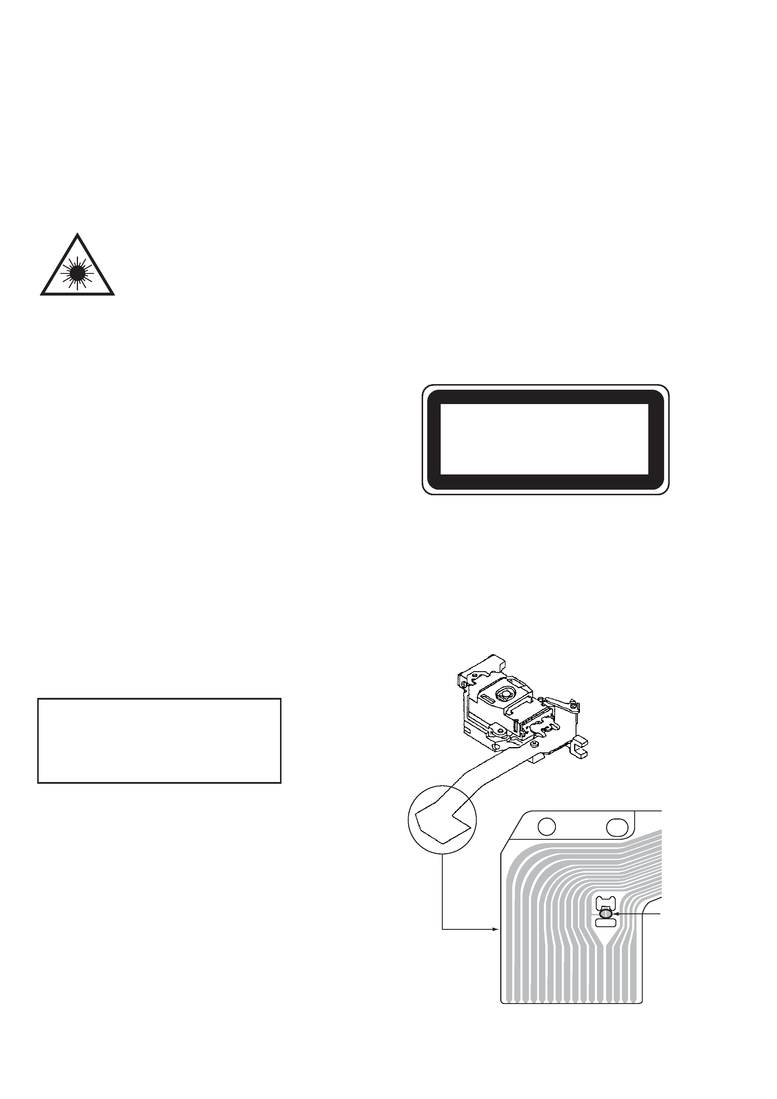
This Compact Disc player is classified as a CLASS 1
LASER product.
The CLASS 1 LASER PRODUCT label is located on the
rear exterior.
PICK-UP ASSY
VED0375-TN
Precaution to replace Optical block
(VED0375-TN)
Body or clothes electrostatic potential could
ruin laser diode in the optical block. Be sure
ground body and workbench, and use care the
clothes do not touch the diode.
1) After the connection, remove solder shown in
right figure.
SOLDER
5
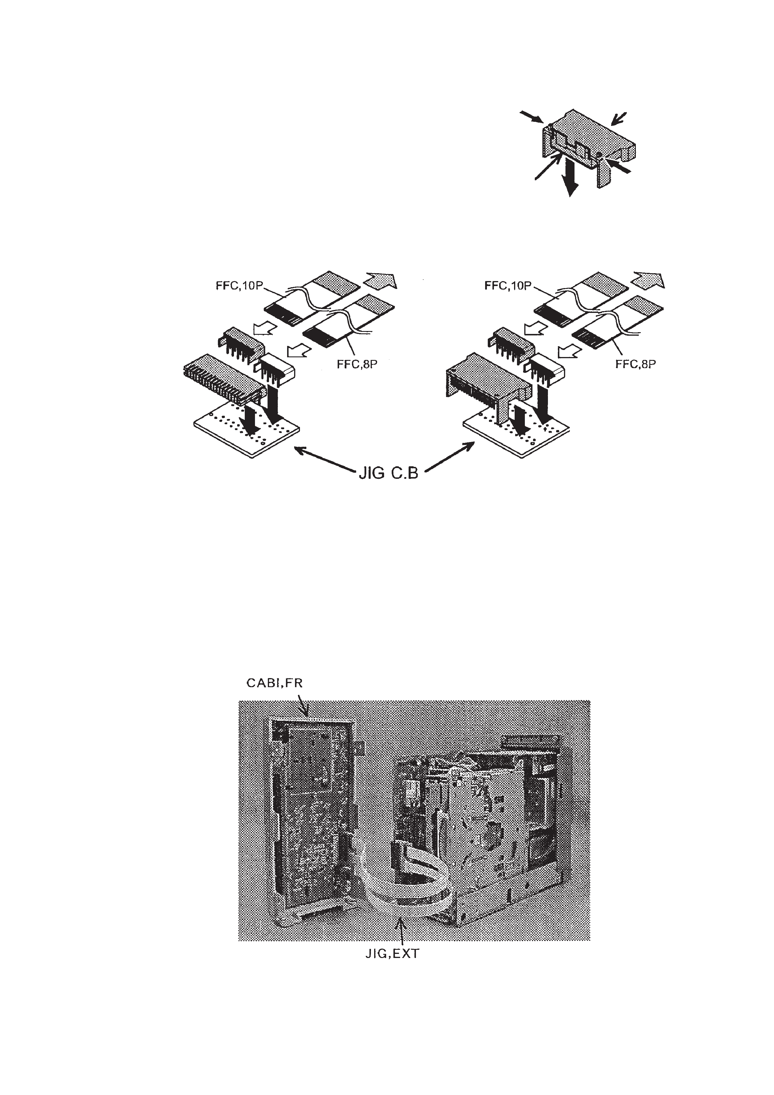
SERVICE JIG AND TOOLS
The distance between the FRONT C.B and the MAIN C.B may be extended with the jig when repairing the FRONT C.B.
Name: JIG, EXT 18P
No.: SV-J00-071-010
1. Assemble Method
1) Remove the solders on the pattern side of JIG C.B.
2) Remove the covers by pushing the picks of sockets (as shown by Fig. 1).
3) Insert and solder the parts into JIG C.B (as shown by Fig. 2).
4) Insert FFC cable into each connector to connect a socket part and a plug part (Fig. 2).
Fig. 1
2. Connection
As shown in the figure below, connect the plug side to the FRONT C.B and the socket side to the MAIN C.B.
· Beware of short circuit on the pattern side of the JIG C.B and FFC coming off.
Fig. 2
Fig. 3