SERVICE MANUAL
DA
TA
MD / CD
STEREO SYSTEM
BASIC CD MECHANISM : DA23L
BASIC MD MECHANISM : AZG-H YA
XR-MD811 EZ
S/M Code No. 09-00C-438-0R1
REVISION
· This Service Manual is the "Revision" and replaces "Simple Manual"
XR-MD811(EZ), (S/M Code No. 09-008-438-0T1).
· If requiring information about the MD mechanism, see Service Manual of
AZG-H, (S/M Code No. 09-005-346-5N2).
XR-MD811
SYSTEM
STEREO
RECEIVER
RX-LMD811
REMOTE
CONTROLLER
RC-AAT21
STEREO MD RECORD/
COMPACT DISC PLAYER
SPEAKER
FM-LMD811
SX-LM810

2
SPECIFICATIONS ................................................................................................................................................. 3
PROTECTION OF EYES FROM LASER BEAM DURING SERVICING ........................................................ 4
DISASSEMBLY INSTRUCTIONS .................................................................................................................... 5 ~ 6
MODEL NO. RX-LMD811
ELECTRICAL MAIN PARTS LIST ................................................................................................................ 7 ~ 9
TRANSISTOR ILLUSTRATION .......................................................................................................................... 10
WIRING 1 (POWER) ......................................................................................................................................... 11
WIRING 2 (PWR-AMP) ..................................................................................................................................... 12
WIRING 3 (PT-MAIN / PT-SUB) ....................................................................................................................... 13
WIRING 4 (TU-INF / JACK) .............................................................................................................................. 14
SCHEMATIC DIAGRAM 1 (POWER / PWR-AMP / PT-MAIN / PT-SUB / TU-INF / JACK) ............................. 15
WIRING 5 (FRONT / LED-1~3) ......................................................................................................................... 16
SCHEMATIC DIAGRAM 2 (FRONT / LED-1~3) .............................................................................................. 17
WIRING 6 (TUNER) .......................................................................................................................................... 18
SCHEMATIC DIAGRAM 3 (TUNER) ............................................................................................................... 19
IC BLOCK DIAGRAM ......................................................................................................................................... 20
LCD DIAGRAM .................................................................................................................................................... 21
ADJUSTMENT ..................................................................................................................................................... 22
MECHANICAL EXPLODED VIEW 1 / 1 ........................................................................................................... 23
MECHANICAL PARTS LIST 1 / 1 ..................................................................................................................... 24
MODEL NO. FM-LMD811
ELECTRICAL MAIN PARTS LIST ............................................................................................................ 25 ~ 27
TRANSISTOR ILLUSTRATION .......................................................................................................................... 28
WIRING 1 (FUNC / KEY / MOTOR / DOOR SW) ............................................................................................. 29
WIRING 2 (FRONT / POWER / LED-L / LED-R) .............................................................................................. 30
SCHEMATIC DIAGRAM 1 (FUNC / FRONT / POWER / KEY / MOTOR / DOOR SW / LED-L / LED-R) ....... 31
WIRING 3 (CD) <1/2> ....................................................................................................................................... 32
WIRING 3 (CD) <2/2> ....................................................................................................................................... 33
SCHEMATIC DIAGRAM 2 (CD) <1/2> ............................................................................................................ 34
SCHEMATIC DIAGRAM 3 (CD) <2/2> ............................................................................................................ 35
IC BLOCK DIAGRAM ......................................................................................................................................... 36
IC DESCRIPTION .......................................................................................................................................37 ~ 42
ADJUSTMENT <MD> .................................................................................................................................. 43 ~ 51
CD TEST MODE .................................................................................................................................................. 52
MD TEST MODE .......................................................................................................................................... 53 ~ 57
MECHANICAL EXPLODED VIEW 1 / 1 ............................................................................................................ 58
MECHANICAL PARTS LIST 1 / 1 ..................................................................................................................... 59
CD MECHANISM EXPLODED VIEW 1 / 1 ...................................................................................................... 60
CD MECHANISM PARTS LIST 1 / 1 ............................................................................................................... 61
GENERAL SPEAKER DISASSEMBLY INSTRUCTIONS (FOR REFERENCE) ............................................. 62
SPEAKER PARTS LIST ..................................................................................................................................... 63
ACCESSORIES / PACKAGE LIST ..................................................................................................................... 63
TABLE OF CONTENTS

3
STEREO RECEIVER RX-LMD811
<FM tuner section>
Tuning range
87.5 MHz to 108 MHz
Usable sensitivity (IHF)
16.8 dBf
Antenna terminals
75 ohms (unbalanced)
<MW tuner section>
Tuning range
531 kHz to 1602 kHz (9 kHz step)
530 kHz to 1710 kHz (10 kHz step)
Usable sensitivity
350
µV/m
Antenna
Loop antenna
<LW tuner section>
Tuning range
144 kHz to 290 kHz
Usable sensitivity
1400
µV/m
Antenna
Loop antenna
<Amplifier section>
Power output
Rated : 16 W + 16 W (6 ohms,
T.H.D. 1 %, 1 kHz/DIN 45500)
Reference : 20 W + 20 W (6 ohms,
T.H.D. 10 %, 1 kHz/DIN 45324)
DIN MUSIC POWER
35 W + 35 W
Outputs
SUPPER WOOFER : 1.0 V
SPEAKERS : accept speakers of
6 ohms or more
PHONES (stereo mini jack) : accepts
headphones of 32 ohms or more
<General>
Power requirements
230 V AC, 50 Hz
Power consumption
60 W
Standby power consumption
16 W (power economizing mode
deactivated)
1.7 W (power economizing mode
activated)
Dimensions of main unit
156 x 114 x 207 mm
(W x H x D)
Weight of main unit
2.8 kg
STEREO MD RECORDER / COMPACT DISC PLAYER
FM-LMD811
<Compact disc player section>
Laser
Semiconductor laser (
= 780 nm)
D-A converter
1 bit dual
Signal-to-noise ratio
85 dB (1 kHz, 0 dB)
Harmonic distortion
0.05 % (1 kHz, 0 dB)
Wow and flutter
Unmeasurable
SPECIFICATIONS
<MD recorder section>
Scanning method
Non-contact optical scanner
(Semiconductor laser application)
Recording system
Magnetic polarity modulation
overwrite system
Rotation speed
Approx. 400 to 900 rpm (CLV)
Sampling frequency
44.1 kHz
No. of channels
Stereo: 2 channels
Monaural: 1 channel
A-D, D-A converter
1-bit
Frequency
20 to 20000 Hz +0.5 - 1.5 dB
Wow and flatter
Unmeasurable
General
Inputs
TAPE IN : 500 mV
AUX IN : 500 mV
DIGITAL IN (OPTICAL) :
Outputs
LINE OUT : 500 mV
Dimensions of main unit
156 x 114 x 200.7 mm
(W x H x D)
Weight of main unit
1.8 kg
SPEAKER SYSTEM SX-LM810
Cabinet type
2 way, bass reflex (magnetic
shielded type)
Speaker
Woofer :
100 mm cone type
Tweeter :
22 mm dome type
Impedance
6 ohms
Output sound pressure level 86 dB/W/m
Dimensions
135 x 223 x 173 mm
(W x H x D)
Weight
1.8 kg
· Design and specifications are subject to change without notice.
· The word "BBE"and the "BBE symbol" are trademarks of BBE
Sound, Inc.
Under license from BBE Sound,Inc.
4
PROTECTION OF EYES FROM LASER BEAM DURING SERVICING
VAROITUS!
Laiteen Käyttäminen muulla kuin tässä käyttöohjeessa mainit-
ulla tavalla saattaa altistaa käyt-täjän turvallisuusluokan 1 ylit-
tävälle näkymättömälle lasersäteilylle.
VARNING!
Om apparaten används på annat sätt än vad som specificeras i
denna bruksanvising, kan användaren utsättas för osynling
laserstrålning, som överskrider gränsen för laserklass 1.
Caution: Invisible laser radiation when
open and interlocks defeated avoid expo-
sure to beam.
Advarsel:Usynling laserståling ved åbning,
når sikkerhedsafbrydere er ude af funktion.
Undgå udsættelse for stråling.
CAUTION
Use of controls or adjustments or performance of procedures
other than those specified herein may result in hazardous
radiation exposure.
ATTENTION
L'utilisation de commandes, réglages ou procédures autres que
ceux spécifiés peut entraîner une dangereuse exposition aux
radiations.
ADVARSEL!
Usynlig laserståling ved åbning, når sikkerhedsafbrydereer ude
af funktion. Undgå udsættelse for stråling.
This Compact Disc player is classified as a CLASS 1 LASER
product.
The CLASS 1 LASER PRODUCT label is located on the rear
exterior.
This set employs laser. Therefore, be sure to follow carefully the
instructions below when servicing.
WARNING!
WHEN SERVICING, DO NOT APPROACH THE LASER EXIT
WITH THE EYE TOO CLOSELY. IN CASE IT IS NECESSARY TO
CONFIRM LASER BEAM EMISSION. BE SURE TO OBSERVE
FROM A DISTANCE OF MORE THAN 30cm FROM THE
SURFACE OF THE OBJECTIVE LENS ON THE OPTICAL
PICK-UP BLOCK.
CLASS 1
KLASSE 1
LUOKAN 1
KLASS 1
LASER PRODUCT
LASER PRODUKT
LASER LAITE
LASER APPARAT
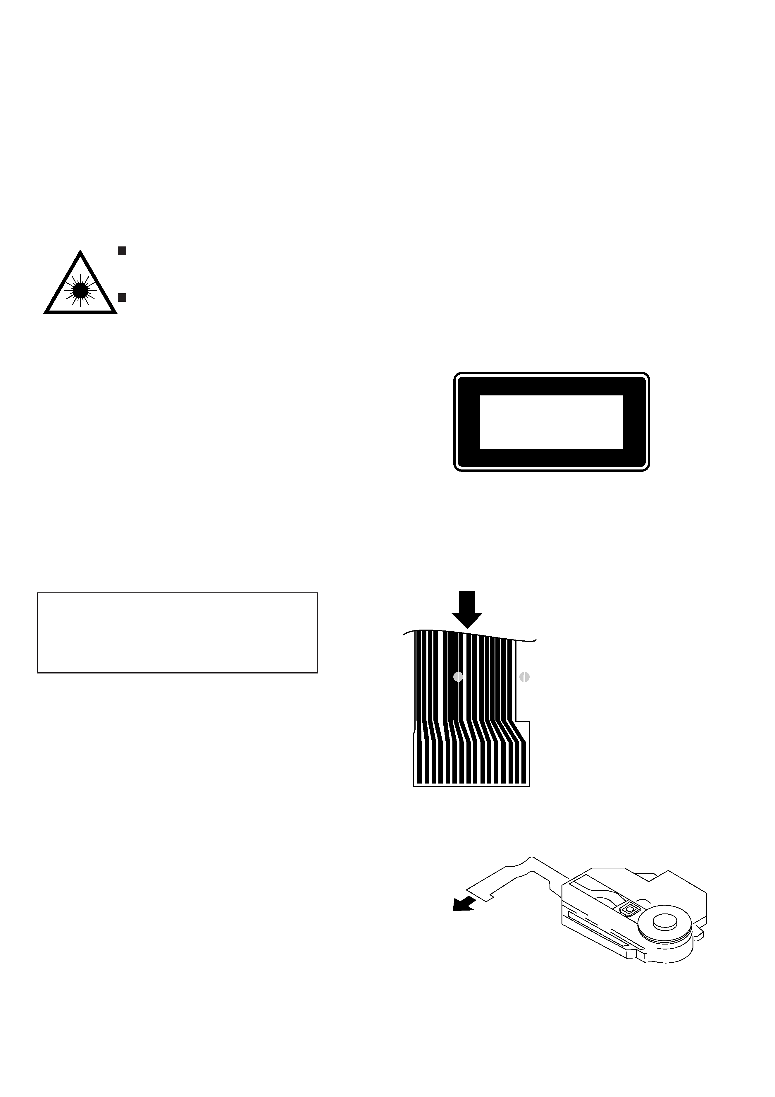
Precaution to replace Optical block
(SF-P200L)
1) After the connection, remove solder shown in
the right figure.
Body or clothes electrostatic potential could ruin
laser diode in the optical block. Be sure ground
body and workbench, and use care the clothes
do not touch the diode.
PICK UP ASSY
: SOLDER
910
15 16
1
5
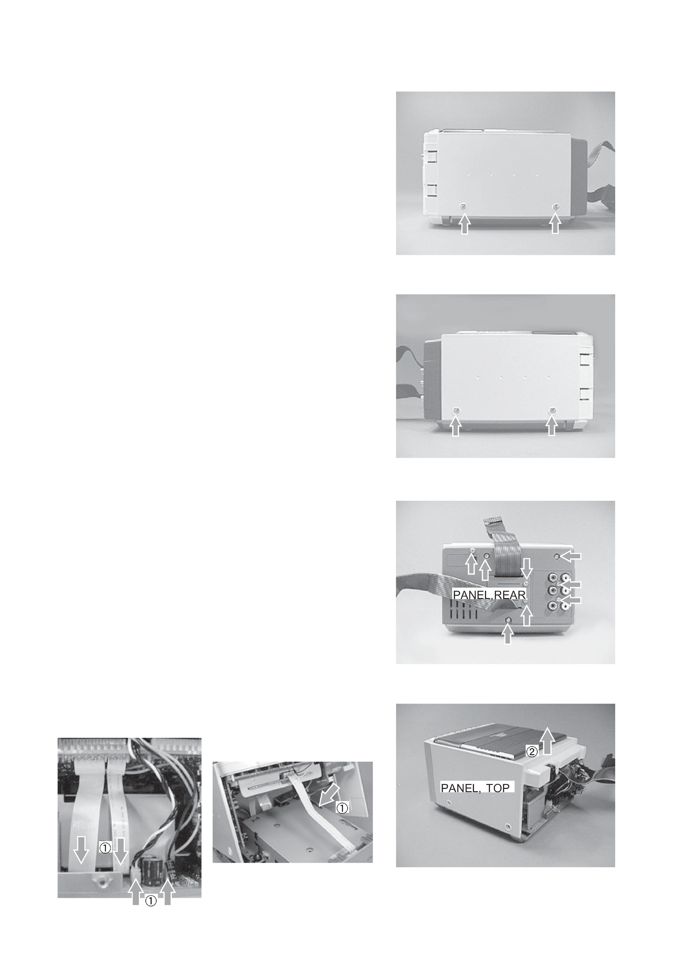
FM BLOCK DISASSEMBLY
1. Removing the Ornament Parts
1)
Remove the two screws.
2)
Remove the two screws.
3)
Remove the eight screws and remove PANEL, REAR.
4)
Remove the FFC from the connector 1 and remove PANEL,
TOP 2.
DISASSEMBLY INSTRUCTIONS