Micro Hi-Fi Component System
4-247-474-61
030601AMI-H-Z
XR-EM200
2
En
On operating voltage
Before operating the system, check that the operating voltage
of your system is identical with the voltage of your local power
supply.
On safety
·The unit is not disconnected from the AC power source
(mains) as long as it is connected to the wall outlet, even if
the unit itself has been turned off.
·Unplug the system from the wall outlet (mains) if it is not to
be used for an extended period of time. To disconnect the
cord (mains lead), pull it out by the plug. Never pull the
cord itself.
·Should any solid object or liquid fall into the component,
unplug the stereo system and have the component checked
by qualified personnel before operating it any further.
·The AC power cord must be changed only at a qualified
service shop.
On placement
·Do not place the unit in an inclined position.
·Do not place the unit in locations where it is;
- Extremely hot or cold
- Dusty or dirty
-Very humid
-Vibrating
- Subject to direct sunlight.
On heat buildup
·Although the unit heats up during operation, this is not
malfunction.
·Place the unit in a location with adequate ventilation to
prevent heat build-up in the unit.
If you continuously use this unit at a large volume, the cabinet
temperature of the top, side and bottom rises considerable.
To avoid burning yourself, do not touch the cabinet.
PRECAUTIONS
WARNING
To prevent fire or shock hazard, do not expose the
unit to rain or moisture.
To avoid electrical shock, do not open the cabinet.
Refer servicing to qualified personnel only.
Do not install the appliance in a confined space, such
as a bookcase or built-in cabinet.
CLASS 1 LASER PRODUCT
LUOKAN 1 LASER LAITE
KLASS 1 LASER APPARAT
This appliance is classified
as a CLASS 1 LASER
product.
This label is located on the
rear exterior.
To prevent fire, do not cover the ventilation of the apparatus
with newspapers, table-cloths, curtains, etc. And don't place
lighted candles on the apparatus.
To prevent fire or shock hazard, do not place objects filled
with liquids, such as vases, on the apparatus.
Don't throw away the battery with
general house waste, dispose of it
correctly as chemical waste.
3
En
On operation
·If the system is brought directly from a cold to a warm
location, or is placed in a very damp room, moisture may
condense on the lens inside the CD player. Should this occur,
the system will not operate properly. Remove the CD and
leave the system turned on for about an hour until the
moisture evaporates.
·When you move the system, take out any discs.
Notes on discs
·Discs recorded on CD-R/RW drives may not be played back
because of scratches, dirt, recording condition or the drive's
characteristics.
·CD-R/RW discs which are not finalized at the end of
recording cannot be played back.
·Do not attach adhesive label to either side of
CD-R/RW discs, as doing so may cause malfunction.
·Do not load an unrecorded CD-R/RW disc. The disc may be
damaged.
·Discs with non-standard shapes (e.g., heart, square, star)
cannot be played on this unit. Attempting to do so may
damage the unit. Do not use such discs.
Music discs encoded with copyright protection
technologies
This product is designed to playback discs that confirm to the
Compact Disc (CD) standard. Recently, various music discs
encoded with copyright protection technologies are marketed
by some record companies.
Please be aware that among those discs, there are some that
do not conform to the CD standard and may not be playable
by this product.
If you have any questions or problems concerning your stereo
system, please consult your nearest Aiwa dealer.
TABLE OF CONTENTS
PRECAUTIONS .................................... 2
PREPARATIONS ................................... 4
PARTS AND CONTROLS ......................... 5
ADJUSTMENTS BEFORE OPERATION .......... 7
CD OPERATIONS .................................. 8
TUNER OPERATIONS ........................... 10
SOUND ADJUSTMENTS ........................ 11
TAPE PLAYBACK ................................ 12
TAPE RECORDING .............................. 13
TIMER OPERATIONS ........................... 14
REFERENCE ..................................... 16
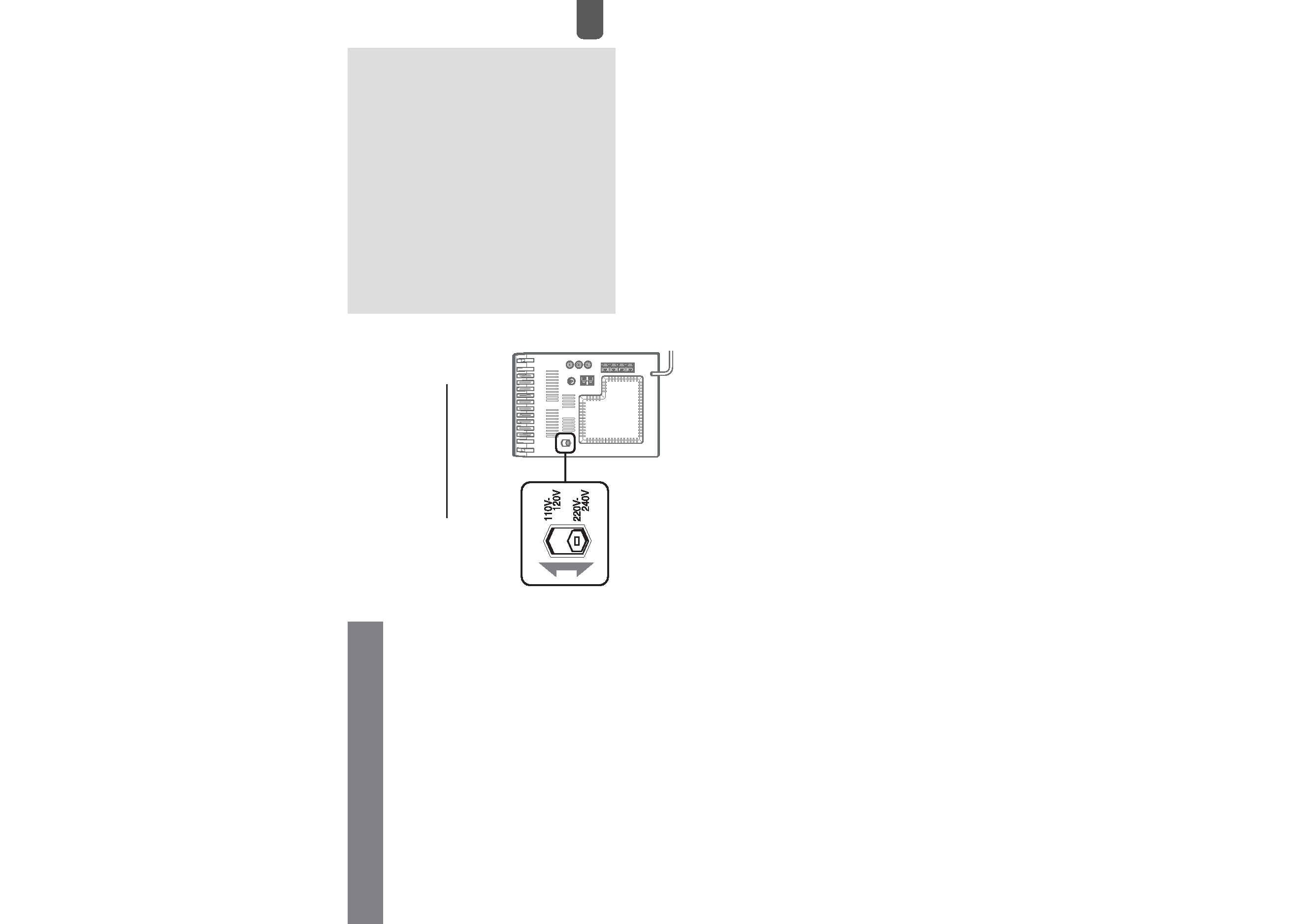
IMPORTANT: Check your AC voltage!!
The unit's AC voltage can be switched between 110 V - 120 V
and 220 V - 240 V.
Before connecting the AC cord, check that
the AC voltage selector, found at the rear of your set, is set
correctly to match your local voltage. If necessary, switch
voltage with a screwdriver or a similar tool.
4
En
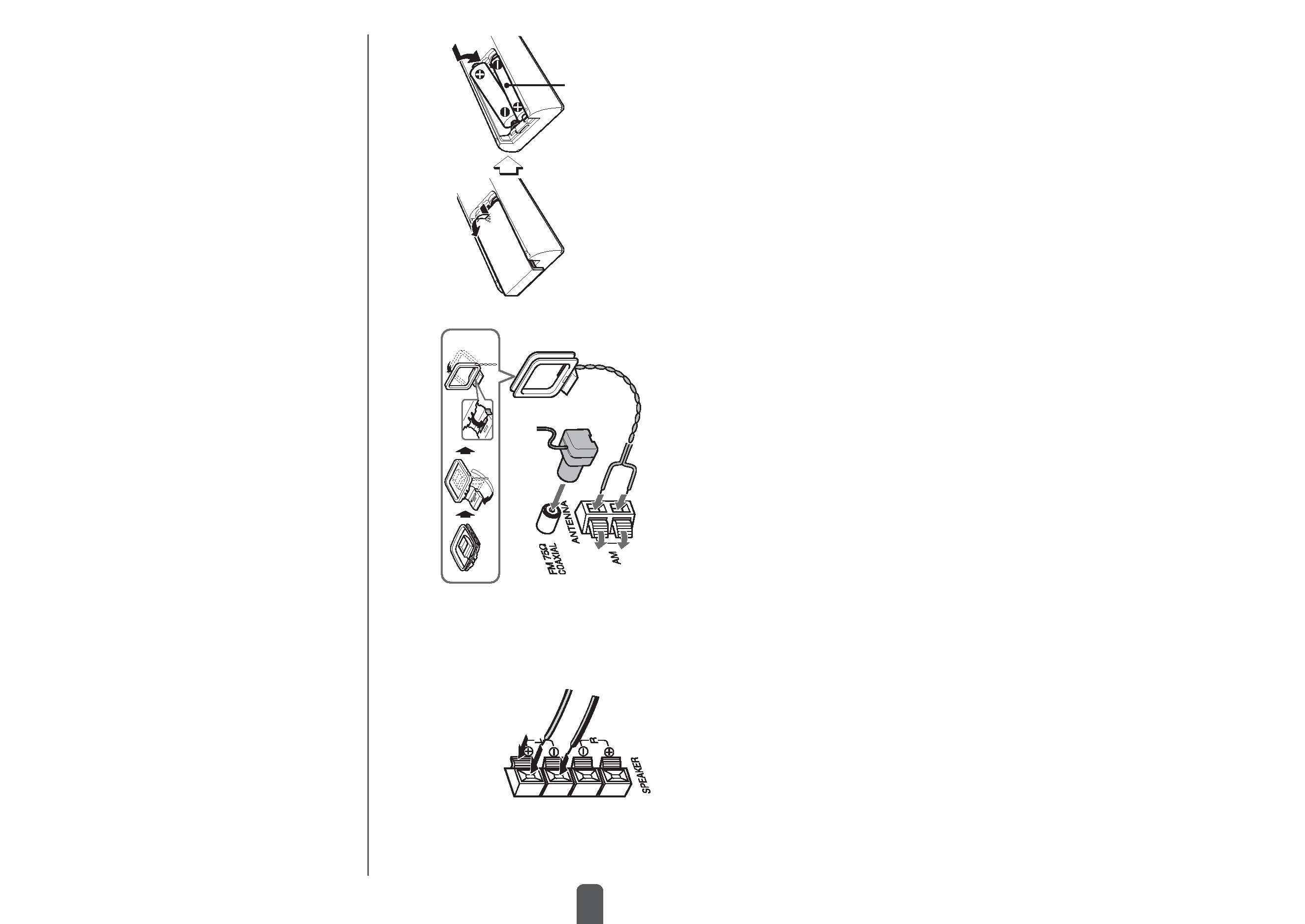
Remote commander
Detach the battery compartment lid at the rear of the remote
commander and insert two R6 (size AA) batteries with correct
polarity.
R6(AA)
·Replace the batteries with new ones when the operational
distance between the remote commander and main unit
becomes shorter.
·Remove the batteries if the unit is not going to be used for
an extended period of time.
·The remote commander may not operate if it is used under
intense sunlight or if its line of sight is obstructed.
Connection
Plug in the AC power cord to the AC outlet after all other
connections are made.
1 Connect the speakers to the main unit.
Connect the right speaker to the SPEAKERS R terminals
and the left to the SPEAKERS L terminals. The speaker
cords with the black stripes go to the ( terminals.
IMPED
ANCE
USE
6-16
PREPARATIONS
2 Connect the supplied antennas.
Connect the FM antenna to the FM 75
terminal and the
AM antenna to the AM jack.
3 Connect the AC power cord to an AC outlet.
The clock will appear in the display.
For setting the clock, see page 7.
Speakers
·Do not short-circuit the ) and ( speaker cord leads.
·Do not leave objects generating magnetism or objects
affected by magnetism near the speakers.
Antennas
Keep antennas away from metallic objects, electrical
equipment and cords.
·FM antenna: Extend fully and position for the best
reception. If reception is poor, connect an optional outdoor
antenna to the FM 75
terminal. Note that, when connecting
an optional outdoor antenna, use an adaptor as required.
·AM antenna: Rotate to find best reception.
5
En
PARTS AND CONTROLS
Main unit: front
Refer to the pages indicated in parentheses for details.
1
2
6
5
4
7
3
8
1 POWER 6STANDBY/ON (7)
Switches the unit on and off (standby).
2 ECO (7)
Sets the ECO mode on or off.
SYNCHRO REC (13)
Starts recording and CD play simultaneously.
REC START/PAUSE (13)
Starts and pauses recording.
DISPLAY (8)
Changes the display in CD playback mode.
3 PHONES jack
Plug in optional headphones set with a stereo mini plug
(ø3.5 mm). Speaker output is cancelled.
4 OPEN (8)
Opens or closes the disc compartment.
5 ECD (7-9)
Starts and pauses CD play.
TUNER/BAND (7, 10)
Selects tuner function and the tuner band.
cTAPE (REC MUTING) (7, 12, 13)
Starts playback.
Also used to enter 4-second blank spaces during
recording.
AUX (7)
Selects the function of external equipment connected to
AUX IN jacks.
6 VOLUME (11, 14)
Adjusts the volume.
7 f/r-, +t/g (8, 10-12, 14, 15)
CD: skips to a previous or a succeeding track when
pressed, searches a track in fast forward or reverse
playback when held down.
Tape: rewinds or fast forwards the tape.
Tuner: manually tunes up or down within the band.
sSTOP (8, 9, 12, 13)
CD and tape: stops playback.
Tuner: clears a preset station.
TONE (11)
Adjusts the bass or treble level.
8 zPUSH EJECT (12, 13)
Opens or closes the cassette holder.
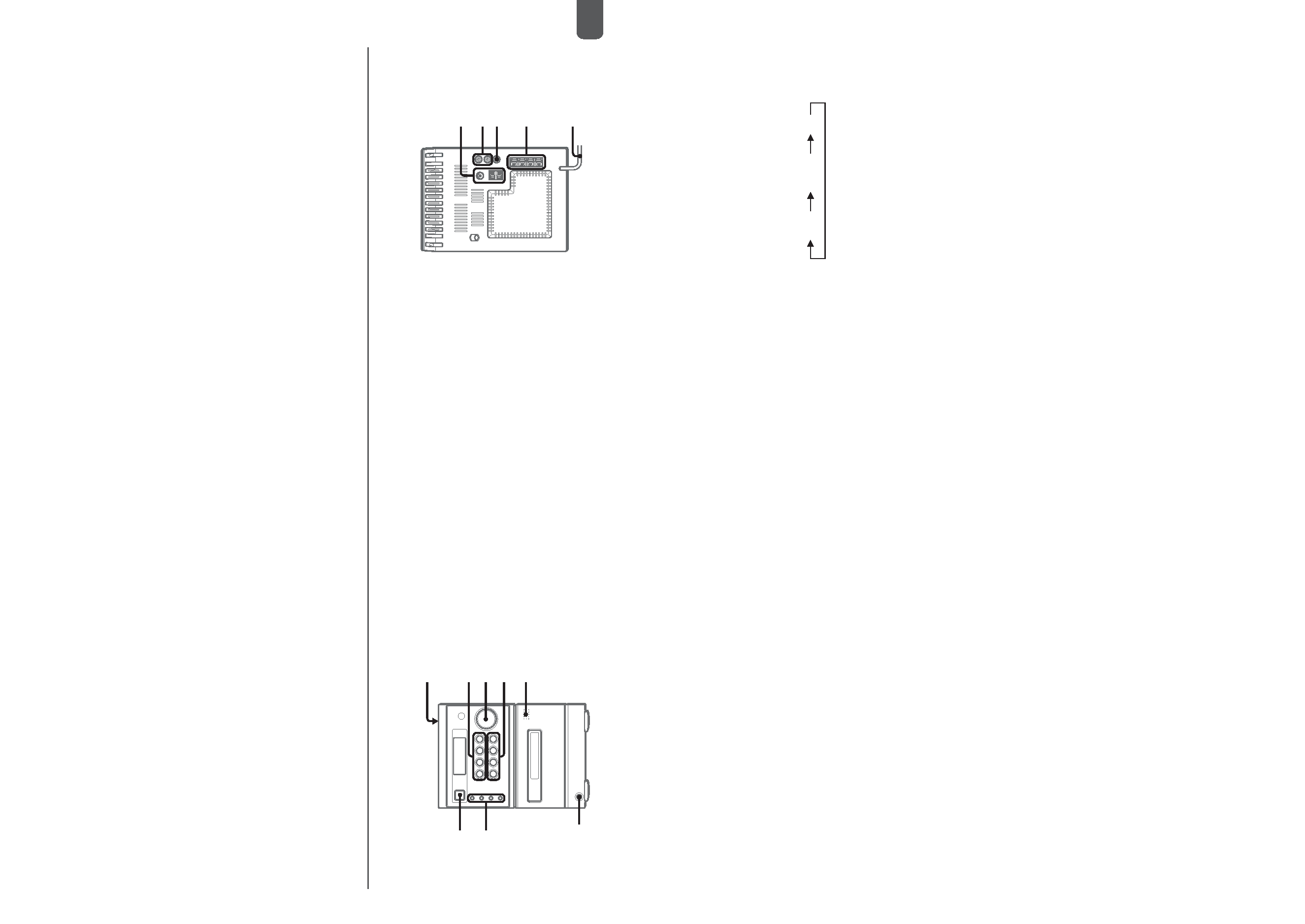
Main unit: rear
Refer to the pages indicated in parentheses for details.
3
4
5
2
1
1 AM jack and FM 75
terminal (4)
Plug in the supplied AM and FM antennas.
2 AUX IN jacks
Accept analog sound signals from external equipment.
Connect external equipment using an optional connecting
cable with RCA phono plugs (red plug to R jack, white
plug to L jack). Refer also to the operating instructions
for your equipment.
To switch function to external input, press AUX.
To change a source name in the display of the
AUX function.
Hold down AUX and press POWER while the power is
on.
AUX
VIDEO
TV
3 SUB WOOFER jack
Connect optional powered sub woofer with a built-in
amplifier to the jack.
4 SPEAKER terminals (4)
Connect the speaker cords of the supplied speakers.
5 AC power cord (4)