SERVICE MANUAL
DA
TA
XRDV526
RCAAS03
SYSTEM
CD
CASSEIVER
REMOTE
CONTROLLER
CXNDV526
DVD STEREO SYSTEM
BASIC TAPE MECHANISM : ZZM-3 YPR1NF
BASIC DVD MECHANISM : AZG-D ZAAPA
XR-DV526
U
S/M Code No. 09-00A-434-1R1
· If requiring information about the DVD mechanism, see Service Manual of AZG-D,
(S/M Code No. 09-00A-350-6N2).
SPEAKERS
SXWNDV526
SXR275
SXC605
· This Service Manual is the "Revision Publishing" and replaces "Simple Manual"
(S/M Code No. 09-007-434-1T1).
REVISION

2
SPECIFICATIONS
Main unit CX-NDV526
<FM Tuner section>
Tuning range
87.5 MHz to 108 MHz
Usable sensitivity (IHF)
13.2 dBf
Antenna terminals
75 ohms (unbalanced)
<AM Tuner section>
Tuning range
530 kHz to 1710 kHz (10 kHz step)
531 kHz to 1602 kHz (9 kHz step)
Usable sensitivity
350
µV/m
Antenna
Loop antenna
<Amplifier section>
Mid-high frequency amplifier
Power output
25 W + 25 W (200 Hz 20 kHz,
THD less than 1 %, 8 ohms)
Total harmonic distortion
0.1 % (15 W, 1 kHz, 8 ohms, DIN
AUDIO)
Low frequency amplifier
Power output
75 W + 75 W (50 Hz 200 Hz,
THD less than 1 %, 6 ohms)
Total harmonic distortion
0.1 % (40 W, 130 Hz, 6 ohms, DIN
AUDIO)
Rear (Surround)
25 W + 25 W
(1 kHz, THD less than 1 %, 8 ohms)
Center
25 W (1 kHz, THD less than 1 %, 8
ohms)
Inputs
VIDEO/AUX: 300 mV (adjustable)
MIC: 1.0 mV (10 k ohms)
Outputs
SPEAKERS HIGH FREQ:
accept speakers of 8 ohms or more
SPEAKERS LOW FREQ:
accept speakers of 6 ohms or more
SURROUND SPEAKERS:
accept speakers of 8 ohms to 16 ohms
CENTER SPEAKER:
accept speakers of 8 ohms or more
SUB WOORER: 1.1 V
DIGITAL AUDIO OUT (OPTICAL)
PHONES (stereo jack): accepts
headphones of 32 ohms or more
<Cassette deck section>
Track format
4 tracks, 2 channels stereo
Frequency response
50 Hz 15000 Hz
Recording system
AC bias
Heads
DECK 1: Playback head x 1
DECK 2: Recording/playback head x 1,
erase head x 1
<Disc player section>
Laser
Semiconductor laser (
=780 nm)
D/A converter
1 bit dual
Signal-to-noise ratio
85 dB (1 kHz, 0 dB)
Harmonic distortion
0.05 % (1 kHz, 0 dB)
Signal format
NTSC
Supported discs
DVD video discs
12 cm (single-sided single-layer, single-
sided double-layer, double-sided-double
layer)
8 cm (single-sided single-layer, single-
sided double-layer, double-sided-double
layer)
Compact discs (CD-DA, CD-R, CD-RW,
video CD)
12 cm and 8 cm discs
S-VIDEO OUT
Y output: 1 Vp-p
(75 ohms, sync negative)
C output: 0.286 Vp-p
VIDEO OUT
Video composit output
1 Vp-p (75 ohms, sync negative)
One RCA jack
Operating conditions
5
°C to 35 °C (41 °F to 95 °F)
<General>
Power requirements
120 V AC, 60 Hz
Power consumption
240 W
Power consumption in standby mode
If the power-economizing mode is
ECO OFF: 40 W
If the power-economizing mode is
ECO ON or ECO AUTO: 0.9 W
Dimensions
260 x 326 x 345 mm
(W x H x D)
(101/4 x 127/8 x 135/8 in.)
Weight
12.5 kg (27 lbs 9 oz.)
Speaker system SX-WNDV526
Speaker system
3 way, Built-in subwoofer
(magnetic shielded type)
Speaker units
Subwoofer:
160 mm (63/8 in.) cone type
Full range:
100 mm (4 in.) cone type
Super tweeter:
20 mm (13/16 in.) ceramic type
Impedance
6 ohms/8 ohms
Sensitivity
87 dB/W/m
Dimensions
240 x 324 x 270 mm
(W x H x D)
(91/2 x 127/8 x 103/4 in.)
Weight
4.8 kg (10 lbs 9 oz.)
· Manufactured under license from Dolby Laboratories Licensing
Corporation.
"DOLBY", the double-D symbol
and "PRO LOGIC" are trademarks
of Dolby Laboratories Licensing Corporation.
· Manufactured under license from Digital Theater Systems, Inc. US
Pat. No. 5,451,942 and other worldwide patents issued and pending.
"DTS" and "DTS Digital Surround" are trademarks of Digital Theater
Systems, Inc. C1996 Digital Theater systems, Inc. All rights reserved.
· Design and specifications are subject to change without notice.
· The word "BBE"and the "BBE symbol" are trademarks of BBE
Sound, Inc.
Under license from BBE Sound,Inc.
3
This set employs laser. Therefore, be sure to follow carefully the
instructions below when servicing.
WARNING!!
WHEN SERVICING, DO NOT APPROACH THE LASER
EXIT WITH THE EYE TOO CLOSELY. IN CASE IT IS
NECESSARY TO CONFIRM LASER BEAM EMISSION.
BE SURE TO OBSERVE FROM A DISTANCE OF MORE
THAN 30cm FROM THE SURFACE OF THE OBJECTIVE
LENS ON THE OPTICAL PICK-UP BLOCK.
Caution: Invisible laser radiation when
open and interlocks defeated avoid
exposure to beam.
Advarsel: Usynlig laserståling ved åbning,
når sikkerhedsafbrydere er ude af funktion.
Undgå udsættelse for stråling.
VAROITUS!
Laiteen Käyttäminen muulla kuin tässä käyttöohjeessa
mainitulla
tavalla
saataa
altistaa
käyt-täjän
turvallisuusluokan 1 ylittävälle näkymättömälle
lasersäteilylle.
VARNING!
Om apparaten används på annat sätt än vad som
specificeras i denna bruksanvising, kan användaren
utsättas för osynling laserstrålning, som överskrider
gränsen för laserklass 1.
PROTECTION OF EYES FROM LASER BEAM DURING SERVICING
CAUTION
Use of controls or adjustments or performance of proce-
dures other than those specified herin may result in
hazardous radiation exposure.
ATTENTION
L'utillisation de commandes, réglages ou procédures
autres que ceux spécifiés peut entraîner une dangereuse
exposition aux radiations.
ADVARSEL
Usynlig laserståling ved åbning, når sikkerhedsafbrydereer
ude af funktion. Undgå udsættelse for stråling.
This Compact Disc player is classified as a CLASS 1
LASER product.
The CLASS 1 LASER PRODUCT label is located on the
rear exterior.
CLASS 1
LASER PRODUCT
KLASSE 1
LASER PRODUKT
LUOKAN 1
LASER LAITE
KLASS 1
LASER APPARAT
(SF HD3AV)
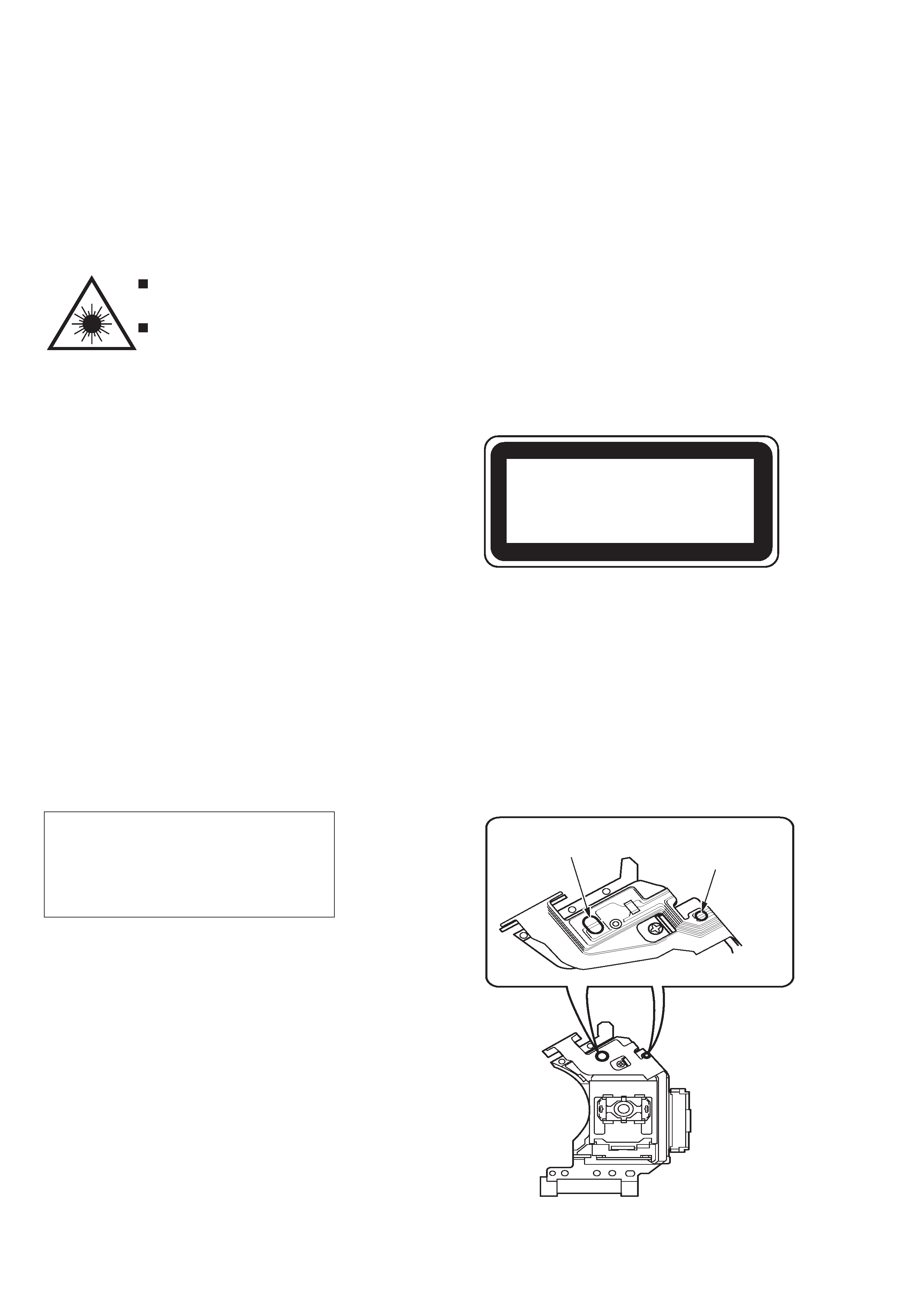
Body or clothes electrostatic potential could
ruin laser diode in the optical block. Be sure
ground body and workbench, and use care
the clothes do not touch the diode.
1) After the connection, remove solder
shown in the right figure.
Precaution to replace Optical block
PICKUP Assy PWB
Solder short land for
DVD laser diode
Solder short land for
CD laser diode
4
NOTE ON BEFORE STARTING REPAIR
Charging voltage (V)
Discharging
Rated power (W)
Parts number
(C101, 102)
resistor (
)
25-48
100
3
87-A00-247-090
49-140
220
5
87-A00-232-090
Note: The reference numbers (C101, C102) of the electrolytic capacitors can change depending on the models. Be sure to check the
reference numbers of the charging capacitors on schematic diagram before starting the discharging work.
2. Check items before exchanging the MICROCOMPUTER
Be sure to check the following items before exchanging the MICROCOMPUTER. Exchange the MICROCOMPUTER after confirming
that the MICROCOMPUTER is surely defective.
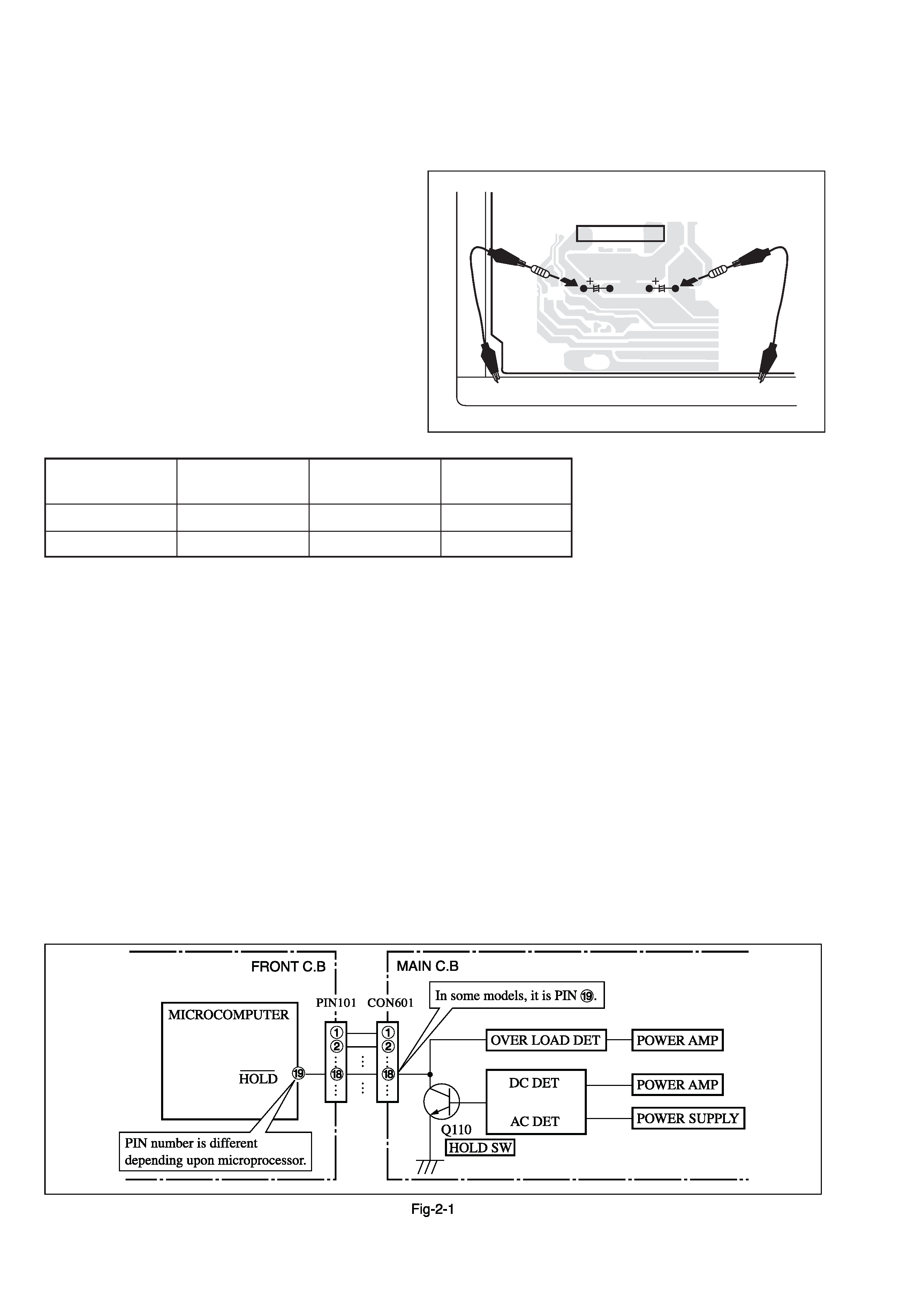
2-1. Regarding the HOLD terminal of the MICROCOMPUTER
When the HOLD terminal (INPUT) of the MICROCOMPUTER is "H", the MICROCOMPUTER is judged to be operating correctly.
When this terminal is "L", the main power cannot be turned on. Therefore, be sure to check the terminal voltage of the HOLD
terminal before exchange.
When the MICROCOMPUTER is not defective, the HOLD terminal can also go "L" when the POWER AMPLIFIER has any
abnormalities that triggers the abnormality detection circuit on the MAIN C. B. that sets the HOLD terminal to "L".
· Good or no good judgement of the MICROCOMPUTER
1
1
1
1
1 Turn on the AC main power.
2
2
2
2
2 Confirm that the main power is turned on and the HOLD terminal of the MICROCOMPUTER keeps the "H" level or not.
3
3
3
3
3 When the HOLD terminal is "L" level, the abnormality detection circuit is judged to be working correctly and the
MICROCOMPUTER is judged to be good.
1. Forced discharge of electrolytic capacitor of power supply block
When repair is going to be attempted in the set that uses relay circuit in the power supply block, electric potential is kept charged across
the electrolytic capacitors (C101, 102) even though AC power cord is removed. If repair is attempted in this condition, secondary defect
can occur.
In order to prevent the secondary trouble, perform the following measures before starting repair work.
Discharge procedure
1
1
1
1
1 Remove the AC power cord.
2
2
2
2
2 Connect a discharging resistor at an end of lead wire that
has clips at both ends. Connect the other end of the lead
wire to metal chassis.
3
3
3
3
3 Contact the other end of the discharging resistor to the
positive (+) side (+VH) of C101. (For two seconds)
4
4
4
4
4 Contact the same end of the discharging resistor as step
3
3
3
3
3 to the negative (-) side (-VH) of C102 in the same way.
(For two seconds)
5
5
5
5
5 Check that voltage across C101 and C102 has decreased
to 1 V or less using a multimeter or an oscilloscope.
Select a discharging resistor referring to the following table.
Fig-1
MAIN C.B
D101
C101
C102
22
3
4
5
In such a case, check also if the POWER AMPLIFIER circuit or power supply circuit has any abnormalities or not.
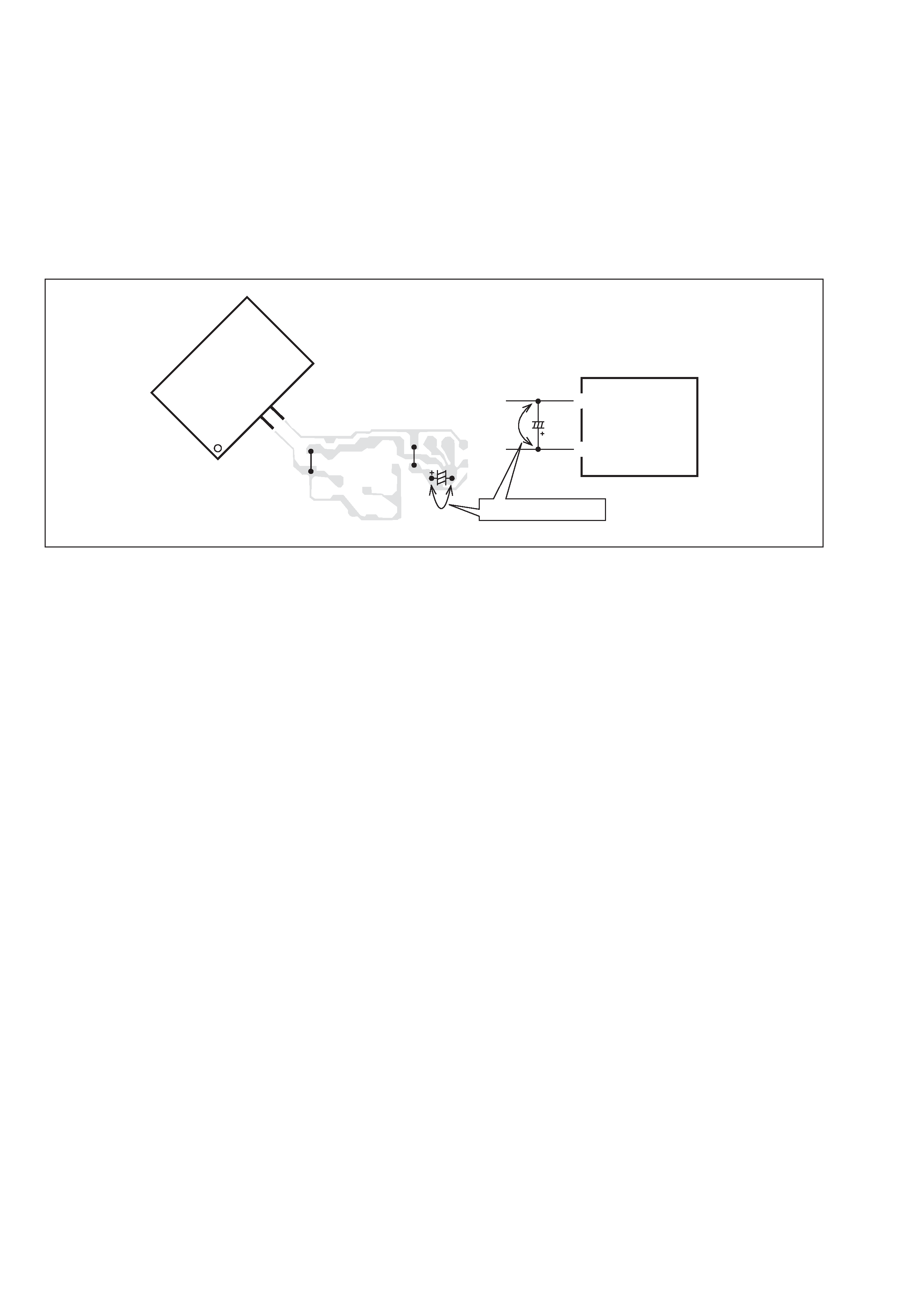
2-2. Regarding reset
There are cases that the machine does not work correctly because the MICROCOMPUTER is not reset even though the AC power
cord is re-inserted, or the software reset (pressing the STOP key + POWER key) is performed.
When the above described phenomenon occurs, it can lead to wrong judgement as if the MICROCOMPUTER is defective and to
exchange the MICROCOMPUTER. In such a case, perform the forced-reset by the following procedure and check good or no
good of the MICROCOMPUTER.
1
1
1
1
1 Remove the AC power cord.
2
2
2
2
2 Short both ends of the electrolytic capacitor C113 that is connected to VDD of the MICROCOMPUTER with tweezers.
3
3
3
3
3 Connect the AC power cord again. If the MICROCOMPUTER returns to the normal operation, the MICROCOMPUTER is
good.
Note: The reference number or MICROCOMPUTER pin number of transistor (Q110) and electrolytic capacitor (C113) can change depending
on the models. Be sure to check the reference numbers on schematic diagram before starting the discharging work.
2-3. Confirmation of soldering state of MICROCOMPUTER
Check the soldering state of the MICROCOMPUTER in addition to the above described procedures. Be sure to exchange the
MICROCOMPUTER after surely confirming that the trouble is not caused by poor soldering but the MICROCOMPUTER itself.
Fig-2-2
MICRO-
COMPUTER
MICR
OCOMPUTER
FRONT C.B
FRONT C.B
VSS
VDD
C113
*
%
C113
18
15
Short with tweezers.