BASIC TAPE MECHANISM : OVD-5
INTEGRATED COLOR TV/VIDEO
CASSETTE RECORDER
VX-G142
S/M Code No. 09-995-325-3O1
K
SERVICE MANUAL
DA
TA
GENERAL
230V AC, 50Hz
79W
12.5 kg (27.5 lbs.)
365(W) x 372(D) x 382(H) mm
(14 3/8 x 14 3/4 x 15 1/8 in.)
14 in. (34cm "V"), 90 degree
Voltage synthesized tuner
UHF: 21 to 69
I
240 lines
5°C to 40°C
Rotary 2 head helical
scanning system
PAL colour system, 625 lines,
50 fields
1 track (Mono)
SPECIFICATIONS
Azimuth 2 head
VHS video cassette
PAL
SP: 23.39mm/sec
LP: 11.69mm/sec
NTSC (Playback SP only)
33.35mm/sec
PAL
SP: 4 hours 20 minutes with
E-260 tape
LP: 8 hours 40 minutes with
E-260 tape
NTSC (Playback SP only)
3 hours with T-180 tape
1.0Vp-p, 75 ohm, unbalanced
1.0Vp-p, 75 ohm, unbalanced
53dB (nominal)
8dBs, 50K ohm
6dBs, less than 1K ohm
VIDEO HEAD ...................................
USABLE CASSETTES .....................
TAPE SPEED ...................................
RECORDING TIME ..........................
VIDEO INPUT ...................................
VIDEO OUTPUT ..............................
VIDEO S/N .......................................
AUDIO INPUT ..................................
AUDIO OUTPUT ..............................
POWER REQUIREMENTS .................
POWER CONSUMPTION ...................
WEIGHT ..............................................
DIMENSIONS ......................................
TV SECTION
PICTURE TUBE DEFLECTION ..........
TUNER SYSTEM ................................
CHANNEL COVERAGE ......................
TV SYSTEM ........................................
HORIZONTAL RESOLUTION ............
VCR SECTION
OPERATING TEMPERATURE ...........
VIDEO RECORDING SYSTEM ..........
VIDEO SIGNAL SYSTEM ...................
AUDIO TRACK ....................................
· Design and specifications are subject to change without
notice.

TABLE OF CONTENTS
SPECIFICATIONS ............................................................................................................................................................
TABLE OF CONTENTS ...................................................................................................................................................
SERVICING NOTICES ON CHECKING ..........................................................................................................................
VCR TEST TAPE INTERCHANGEABILITY TABLE ........................................................................................................
DISASSEMBLY INSTRUCTIONS
REMOVAL OF MECHANICAL PARTS AND P.C. BOARDS .........................................................................................
REMOVAL OF DECK PARTS .......................................................................................................................................
REMOVAL OF ANODE CAP .........................................................................................................................................
KEY TO ABBREVIATIONS ..............................................................................................................................................
PREVENTIVE CHECKS AND SERVICE INTERVALS ....................................................................................................
NOTE FOR THE REPLACING OF MEMORY IC .............................................................................................................
DECK PARTS LOCATIONS .............................................................................................................................................
SERVICING FIXTURES AND TOOLS .............................................................................................................................
PREPARATION FOR SERVICING ..................................................................................................................................
ADJUSTMENTS
MECHANICAL ADJUSTMENTS ...................................................................................................................................
MAJOR COMPONENTS LOCATION GUIDE (VCR) ....................................................................................................
ELECTRICAL ADJUSTMENTS (VCR) .........................................................................................................................
MAJOR COMPONENTS LOCATION GUIDE (TV) .......................................................................................................
ELECTRICAL ADJUSTMENTS (TV) ............................................................................................................................
TROUBLESHOOTING GUIDES .......................................................................................................................................
IC DESCRIPTIONS ..........................................................................................................................................................
SERVO TIMING CHART ..................................................................................................................................................
SYSTEM SWITCH MODE ................................................................................................................................................
SEMICONDUCTOR BASE CONNECTIONS ...................................................................................................................
BLOCK DIAGRAMS
TV ..................................................................................................................................................................................
Y/C/HEAD AMP .............................................................................................................................................................
SYSTEM CONTROL/OPERATION/POWER/IN/OUT ...................................................................................................
TUNER/AUDIO/IF ..........................................................................................................................................................
PRINTED CIRCUIT BOARDS (OPERATION 1/HEAD AMP/IF) .......................................................................................
OPERATION 1 SCHEMATIC DIAGRAM .........................................................................................................................
HEAD AMP SCHEMATIC DIAGRAM ...............................................................................................................................
IF SCHEMATIC DIAGRAM ..............................................................................................................................................
PRINTED CIRCUIT BOARDS (SYSCON) .......................................................................................................................
Y/C SCHEMATIC DIAGRAM ............................................................................................................................................
SYSTEM CONTROL SCHEMATIC DIAGRAM ................................................................................................................
TUNER/AUDIO SCHEMATIC DIAGRAM .........................................................................................................................
POWER/IN/OUT SCHEMATIC DIAGRAM .......................................................................................................................
MICON SCHEMATIC DIAGRAM ......................................................................................................................................
CHROMA SCHEMATIC DIAGRAM .................................................................................................................................
SOUND AMP SCHEMATIC DIAGRAM ............................................................................................................................
OPERATION SCHEMATIC DIAGRAM ............................................................................................................................
PRINTED CIRCUIT BOARDS (MAIN/CRT/POWER SW/EARPHONE) ...........................................................................
DEFLECTION SCHEMATIC DIAGRAM ...........................................................................................................................
POWER SCHEMATIC DIAGRAM ....................................................................................................................................
CRT SCHEMATIC DIAGRAM ..........................................................................................................................................
EARPHONE SCHEMATIC DIAGRAM .............................................................................................................................
INTERCONNECTION DIAGRAM .....................................................................................................................................
WAVEFORMS ..................................................................................................................................................................
MECHANICAL EXPLODED VIEW ...................................................................................................................................
MECHANICAL REPLACEMENT PARTS LIST ................................................................................................................
ACCESSORY REPLACEMENT PARTS LIST .................................................................................................................
CHASSIS EXPLODED VIEW (TOP VIEW) ......................................................................................................................
CHASSIS EXPLODED VIEW (BOTTOM VIEW) ..............................................................................................................
FRONT LOADING UNIT 9 EXPLODED VIEW .................................................................................................................
CHASSIS/FRONT LOADING UNIT 9 REPLACEMENT PARTS LIST ..............................................................................
ELECTRICAL REPLACEMENT PARTS LIST ..................................................................................................................
COVER
A-1
A-2
A-3
B1-1, B1-2
B2-1~B2-5
B3-1
C1-1, C1-2
C2-1
C3-1
C4-1, C4-2
C5-1
C5-2
D1-1~D1-3
D2-1
D2-2, D2-3
D3-1
D3-2~D3-5
E-1~E-27
F-1~F-5
G-1
G-2
H-1
I-1
I-2
I-3
I-4
J-1~J-3
J-4
J-5
J-6
J-7~J-9
J-10
J-11
J-12
J-13
J-14
J-15
J-16
J-17
J-18
J-19
J-20
J-21
J-22
J-23
K-1, K-2
L1-1, L1-2
L2-1
L2-1
M1-1
M1-2
M1-3
M2-1
N-1~N-5
A-1

SERVICING NOTICES ON CHECKING
1. KEEP THE NOTICES
2. AVOID AN ELECTRIC SHOCK
As for the places which need special attentions, they are
indicated with the labels or seals on the cabinet, chassis
and parts. Make sure to keep the indications and notices
in the operation manual.
There is a high voltage part inside. Avoid an electric
shock while the electric current is flowing.
3. USE THE DESIGNATED PARTS
The parts in this equipment have the specific
characters of incombustibility and withstand voltage for
safety. Therefore, the part which is replaced should be
used the part which has the same character.
Especially as to the important parts for safety which is
indicated in the circuit diagram or the table of parts as
a
mark, the designated parts must be used.
6. AVOID AN X-RAY
Safety is secured against an X-ray by considering about
the cathode-ray tube and the high voltage
peripheral circuit, etc.
Therefore, when repairing the high voltage peripheral
circuit, use the designated parts and make sure not
modify the circuit.
Repairing except indicates causes rising of high
voltage, and it emits an X-ray from the cathode-ray tube.
4. PUT PARTS AND WIRES IN THE ORIGINAL
POSITION AFTER ASSEMBLING OR WIRING
There are parts which use the insulation material such
as a tube or tape for safety, or which are assembled in
the condition that these do not contact with the printed
board. The inside wiring is designed not to get closer to
the pyrogenic parts and high voltage parts. Therefore,
put these parts in the original positions.
5. TAKE CARE TO DEAL WITH THE
CATHODE-RAY TUBE
In the condition that an explosion-proof cathode-ray
tube is set in this equipment, safety is secured against
implosion. However, when removing it or serving from
backward, it is dangerous to give a shock. Take
enough care to deal with it.
PERFORM A SAFETY CHECK AFTER
SERVICING
7.
Confirm that the screws, parts and wiring which were
removed in order to service are put in the original
positions, or whether there are the portions which are
deteriorated around the serviced places serviced or not.
Check the insulation between the antenna terminal or
external metal and the AC cord plug blades. And be sure
the safety of that.
(INSULATION CHECK PROCEDURE)
1.
2.
3.
4.
Unplug the plug from the AC outlet.
Remove the antenna terminal on TV and turn on the
TV.
Insulation resistance between the cord plug terminals
and the eternal exposure metal [Note 2] should be
more than 1M ohm by using the 500V insulation resis-
tance meter [Note 1].
If the insulation resistance is less than 1M ohm, the
inspection repair should be required.
[Note 1]
If you have not the 500V insulation resistance meter,
use a Tester.
[Note 2]
External exposure metal: Antenna terminal
Earphone jack
A-2
TTV-P16
TTV-P7
TTV-P2
TTV-P1L
TTV-P1
TTV-N7A
TTV-N2
TTV-N1E
TTV-N1
NTSC
NTSC, Color,
1kHz, SP
NTSC, Color,
1kHz, EP
NTSC, Color,
1kHz, SP
PAL, Color,
1kHz, SP
PAL, Color,
1kHz, LP
PAL, Stairsteps,
1kHZ, SP, HiFi,
1kHz
NTSC, Stairsteps,
7kHz, SP
NTSC, Stairsteps,
1kHz, SP, HiFi
400Hz
TTV-N12
(SCV-1998)
CH-2(3)
CH-2(1)
CH-2(4)
CH-1B(3)
CH-1B(4)
CH-1B(1)
CH-1B(4)
*2
CH-1B(2)
NTSC, Stairsteps,
1kHz, SP
NTSC, Color,
1kHz, EP
NTSC, Stairsteps,
7kHz, SP
NTSC, Color,
1kHz, EP
PAL, Stairsteps,
1kHz, SP
CH-2(2)
*3
PAL, Color,
1kHz, LP
PAL, Stairsteps,
6kHz, SP
PAL, Stairsteps,
6kHz, SP
PAL, Color, No
sound SP, HiFi
400Hz
*1. Described in the order of color format. Video signal. Linear audio. Tape speed and Hi-Fi audio.
*2. Use CH-1B (1) - (3) with models used exclusively in the SP mode.
*3. Use CH-2 (3) and (4) when it is necessary to observe the chroma signal.
There are two types of the new alignment tape CH-1B (for NTSC) and CH-2 (for PAL). On each tape four signals (1) - (4) are
recorded for the times and in the order shown below.
The TTV-MP1 (for M-PAL), TTV-MS1 (for MESECAM) and TTV-S1 (for SECAM) alignment tapes have the same contents as
the previous tapes.
(1) : 8min. ---> (2) : 2min. ---> (3) : 5min. ---> (4) : 5min.
Method
Contents*1
Model
Model
Contents*1
Application
Now in use TYPE
New TYPE
No Changed.
PB-Y Level/General electrical ADJ.
Head ACE Height/Tilt ADJ.
HiFi Audio PB Level ADJ.
Switching position. (LP Model)
FM Envelope ADJ. (LP Model)
X-Value ADJ. (LP Model)
Head ACE Azimuth ADJ.
FM Envelope ADJ. (SP Model)
X-Value ADJ. (SP Model)
HiFi Audio PB Level ADJ.
FM Filter ADJ.
FM envelope ADJ.
X-Value ADJ.
Head ACE Azimuth ADJ.
Switching position ADJ.
PAL
VCR TEST TAPE INTERCHANGEABILITY TABLE
Switching position ADJ.
PB-Y Level/General electrical ADJ.
Head ACE Height/Tilt ADJ.
PAL, Color, 400Hz,
SP, HiFi 1kHz
NTSC, Color, No
sound SP, HiFi
400Hz
A-3
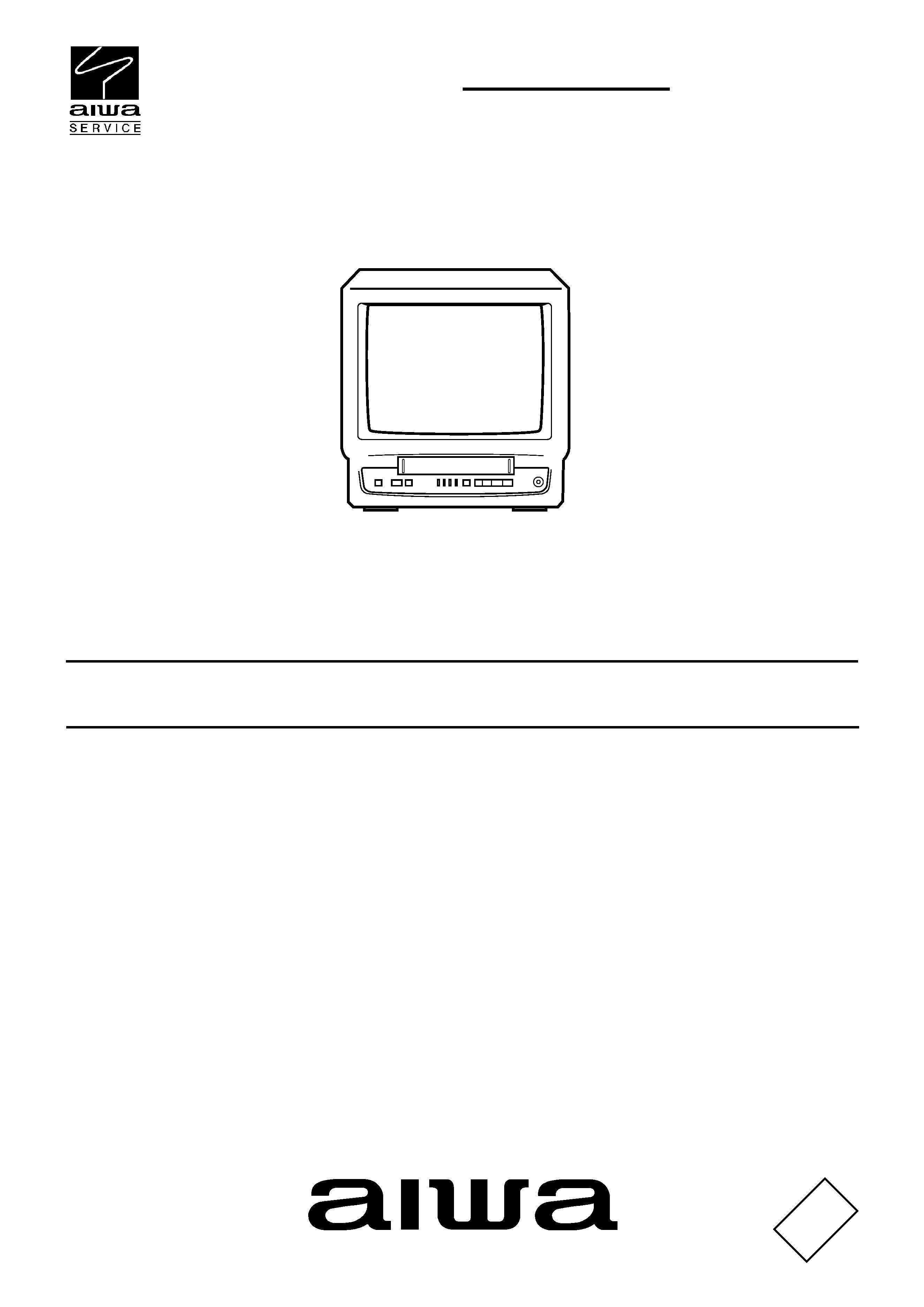
DISASSEMBLY INSTRUCTIONS
1. REMOVAL OF MECHANICAL PARTS
AND P.C. BOARDS
1-1: BACK CABINET (Refer to Fig. 1-1)
1.
2.
3.
Remove the 4 screws 1.
Remove the 2 screws 2.
Remove the Back Cabinet in the direction of arrow.
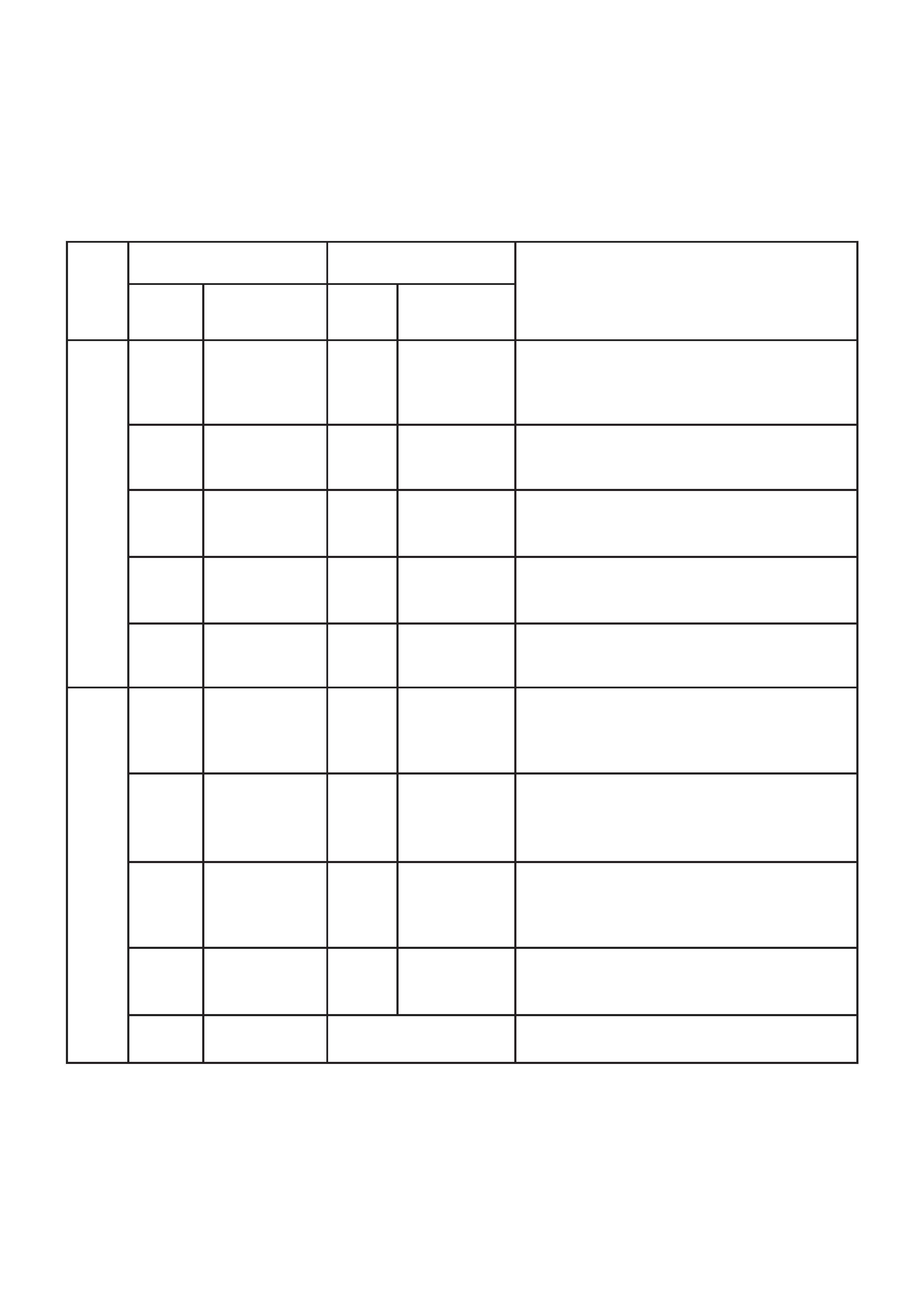
(B)
TV Block
CRT PCB
(A)
Fig. 1-2
Front Cabinet
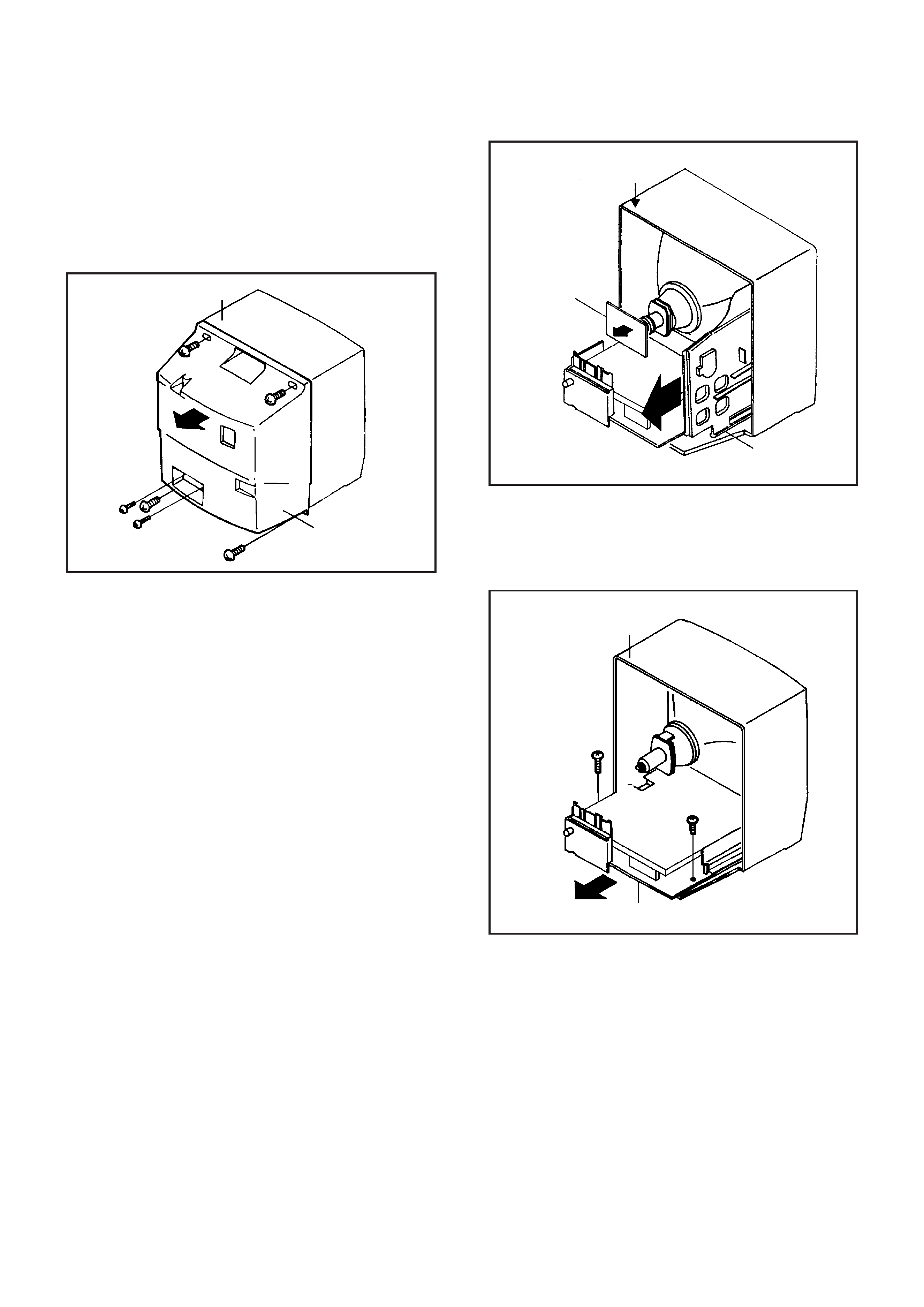
1-3: VCR BLOCK (Refer to Fig. 1-3)
Remove the 2 screws 1.
Unlock the support 2.
Remove the VCR Block in the direction of arrow.
1.
2.
3.
VCR Block
Front Cabinet
2
1
1
Fig. 1-3
Front Cabinet
Back Cabinet
1
2
2
1
1
1
Fig. 1-1
CAUTION: BEFORE REMOVING THE ANODE CAP,
DISCHARGE ELECTRICITY BECAUSE IT
CONTAINS HIGH VOLTAGE.
BEFORE ATTEMPTING TO REMOVE OR
REPAIR ANY PCB, UNPLUG THE POWER
CORD FROM THE AC SOURCE.
1-2: TV BLOCK (Refer to Fig. 1-2)
1.
2.
3.
4.
Remove the CRT PCB in the direction of arrow (A), then
unplug the following connector: (CP801 and CP850).
Remove the Anode Cap.
(Refer to REMOVAL OF ANODE CAP)
Disconnect the following connectors:
(CP820, CP810, CP005, CP502 and CP503).
Slide out the TV Block in the direction of arrow (B).
The speaker cannot be removed before removing the
Earphone PCB.
B1-1