SERVICE MANUAL
DA
TA
DVD COLOR TELEVISION
VX-F20DV1 U
S/M Code No. 09-009-437-0R1
REVISION
· This Service Manual is the "Revision Publishing" and replaces "Simple
Manual" (S/M Code No. 09-008-437-0T1).
· If requiring information about DVD mechanism, see Service Manual of
AZG-D, (S/M Code No. 09-00A-350-6N4)
BASIC DVD MECHANISM : AZG-D ZDADM

2
TABLE OF CONTENT
SPECIFICATIONS ................................................................................................................................................................ 3
ACCESSORIES / PACKAGE LIST ...................................................................................................................................... 3
PROTECTION OF EYES FROM LASER BEAM DURING SERVICING ........................................................................ 4
NOTICES BEFORE REPAIRING .................................................................................................................................... 5, 6
DISASSEMBLY INSTRUCTIONS ................................................................................................................................ 7 ~ 20
SERVICE POSITION ......................................................................................................................................................... 21
WIRE ARRANGEMENT ............................................................................................................................................. 22 ~ 27
ELECTRICAL MAIN PARTS LIST ........................................................................................................................... 28 ~ 34
TRANSISTOR ILLUSTRATION ......................................................................................................................................... 35
WIRING 1 (MAIN) ........................................................................................................................................................... 36
SCHEMATIC DIAGRAM 1 (MAIN) ................................................................................................................................. 37
WIRING 2 (AUDIO) ......................................................................................................................................................... 38
SCHEMATIC DIAGRAM 2 (AUDIO) .............................................................................................................................. 39
WIRING 3 (NK) ............................................................................................................................................................... 40
SCHEMATIC DIAGRAM 3 (NK) ..................................................................................................................................... 41
WIRING 4 (S-JACK) ........................................................................................................................................................ 42
SCHEMATIC DIAGRAM 4 (S-JACK) ............................................................................................................................. 43
WIRING 5 (JOINT) .......................................................................................................................................................... 44
SCHEMATIC DIAGRAM 5 (JOINT) ............................................................................................................................... 45
WIRING 6 (SYSTEM) ...................................................................................................................................................... 46
SCHEMATIC DIAGRAM 6 (SYSTEM) ........................................................................................................................... 47
WIRING 7 (FR-JACK) ..................................................................................................................................................... 48
SCHEMATIC DIAGRAM 7 (FR-JACK) ........................................................................................................................... 49
WIRING 8 (FR-KEY) ....................................................................................................................................................... 50
SCHEMATIC DIAGRAM 8 (FR-KEY) ............................................................................................................................. 51
WIRING 9 (OPT) ............................................................................................................................................................. 52
SCHEMATIC DIAGRAM 9 (OPT) .................................................................................................................................. 53
WIRING 10 (PS-2) .......................................................................................................................................................... 54
SCHEMATIC DIAGRAM 10 (PS-2) ................................................................................................................................. 55
WIRING 11 (PS-SW) ....................................................................................................................................................... 56
SCHEMATIC DIAGRAM 11 (PS-SW) ............................................................................................................................. 57
WIRING 12 (FR-FL) ........................................................................................................................................................ 58
SCHEMATIC DIAGRAM 12 (FR-FL) ............................................................................................................................... 59
IC BLOCK DIAGRAM ................................................................................................................................................ 60 ~ 61
FL (10-BT-207GK) GRID ASSIGNMENT AND ANODE CONNECTION .............................................................. 62 ~ 63
IC DESCRIPTION ...................................................................................................................................................... 64 ~ 67
VOLTAGE CHART ...................................................................................................................................................... 68 ~ 75
WAVEFORM ............................................................................................................................................................... 76 ~ 81
ELECTRICAL ADJUSTMENT .................................................................................................................................... 82 ~ 96
ON THE DEFAULT MODE WHEN SHIPPED FROM THE FACTORY .......................................................................97
DVD TEST MODE ............................................................................................................................................................. 98
MECHANICAL EXPLODED VIEW 1 / 1 ........................................................................................................................... 99
MECHANICAL PARTS LIST 1 / 1 .................................................................................................................................. 100

3
SPECIFICATIONS
TV SECTION
Tuner System
Frequency synthesized tuner
TV System
NTSC-M
Channel Coverage
VHF: 2 to 13
UHF: 14 to 69
CATV: 5A, A-1 to A-5, A to W,
W+1 to W+84
Program Memory
181
Antenna Input
75 ohms, unbalanced
Picture Tube
20 in.
Screen Size
406 (W) x 305 (H) mm
(16 x 121/8 in.)
508 mm (diagonal) (20 in.)
Video Input
1 Vp-p, 75 ohms
Audio Input
0.5 Vrms., more than 33 k ohms
Video output
1 Vp-p, 75 ohms (sync negative)
Audio output
0.5 Vrms., 2.2 k ohms
Digital Audio output
Optical
Speaker
160 x 40 mm (63/8 x 15/8 in.)
DISC PLAYER SECTION
Laser
Semiconductor laser
( =650 /780 nm)
D/A converter
1 bit dual
Signal format
NTSC
Supported discs
DVD video discs
12 cm (single-sided single-layer,
single-sided double-layer,
double-sided single-layer,
double-sided double layer)
8 cm (single-sided single-layer,
single-sided double-layer,
double-sided single-layer,
double-sided double layer)
Compact discs (CD-DA, video CD)
12 cm and 8 cm discs
· Design and specifications are subject to change without
notice.
ACCESSORIES / PACKAGE LIST
DESCRIPTION
REF. NO.
KANRI
NO.
PART NO.
1
8A-JD1-670-010
RC UNIT,RC-AVC01
2
8A-JD1-901-010
IB,U (3L)
3
8A-JD1-904-010
IB,U QUICK (E/S/F)
4
87-B30-311-010
ADAPTOR,300 75 TSN-02
· Manufactured under license from Dolby Laboratories Licensing
Corporation.
"DOLBY", the double-D symbol
and "PRO LOGIC" are
trademarks of Dolby Laboratories Licensing Corporation.
GENERAL
Operating Voltage
120 V AC, 60 Hz
Power Consumption
125 W
Phones Jack
Stereo-mini jack
Operating Temperature
5
°C 35 °C
Operating Humidity
35 % 80 %
Dimensions
575 (W) x 504 (H) x 493(D) mm
(223/4 x 197/8 x 191/2 in.)
Weight
30.0 kg (66 lbs.)
· Manufactured under license from Digital Theater System, Inc. US
Pat. No. 5,451,942 and other worldwide patents issued and pending.
"DTS" and "DTS Digital Surround" are trademarks of Digital Theater
System Inc. C1996 Digital Theater system, Inc. All rights reserved.

4
This set employs laser. Therefore, be sure to follow carefully the
instructions below when servicing.
WARNING!!
WHEN SERVICING, DO NOT APPROACH THE LASER
EXIT WITH THE EYE TOO CLOSELY. IN CASE IT IS
NECESSARY TO CONFIRM LASER BEAM EMISSION.
BE SURE TO OBSERVE FROM A DISTANCE OF MORE
THAN 30cm FROM THE SURFACE OF THE OBJECTIVE
LENS ON THE OPTICAL PICK-UP BLOCK.
Caution: Invisible laser radiation when
open and interlocks defeated avoid
exposure to beam.
Advarsel: Usynlig laserståling ved åbning,
når sikkerhedsafbrydere er ude af funktion.
Undgå udsættelse for stråling.
VAROITUS!
Laiteen Käyttäminen muulla kuin tässä käyttöohjeessa
mainitulla
tavalla
saataa
altistaa
käyt-täjän
turvallisuusluokan 1 ylittävälle näkymättömälle
lasersäteilylle.
VARNING!
Om apparaten används på annat sätt än vad som
specificeras i denna bruksanvising, kan användaren
utsättas för osynling laserstrålning, som överskrider
gränsen för laserklass 1.
PROTECTION OF EYES FROM LASER BEAM DURING SERVICING
CAUTION
Use of controls or adjustments or performance of proce-
dures other than those specified herin may result in
hazardous radiation exposure.
ATTENTION
L'utillisation de commandes, réglages ou procédures
autres que ceux spécifiés peut entraîner une dangereuse
exposition aux radiations.
ADVARSEL
Usynlig laserståling ved åbning, når sikkerhedsafbrydereer
ude af funktion. Undgå udsættelse for stråling.
This Compact Disc player is classified as a CLASS 1
LASER product.
The CLASS 1 LASER PRODUCT label is located on the
rear exterior.
CLASS 1
LASER PRODUCT
KLASSE 1
LASER PRODUKT
LUOKAN 1
LASER LAITE
KLASS 1
LASER APPARAT
(SF HD3AV)
Body or clothes electrostatic potential could
ruin laser diode in the optical block. Be sure
ground body and workbench, and use care
the clothes do not touch the diode.
1) After the connection, remove solder
shown in the right figure.
Precaution to replace Optical block
PICKUP ASSY PWB
Solder short land for
DVD laser diode
Solder short land for
CD laser diode
5
When servicing and checking on the TV, note the followings.
NOTICES BEFORE REPAIRING
To make the best use of this equipment, make sure to
obey the following items when repairing (or mending).
1. Do not damage or melt the tunicate of the leading
wire on the AC1 side, including the power supply
cord.
2. Do not soil or stain the letters on the spec.
inscription plates, notice labels, fuse labels, etc.
3. When repairing the part extracted from the
conducted side of the board pattern, fix it firmly
with applying bond to the pattern and the part.
4. Restore the following items after repairing.
1) Conditions of soldering of the wires (especially,
the distance on the AC1 side).
2) Conditions of wiring, bundling of wires, etc.
3) Types of the wries.
4) Attachment conditions of all types of the insulation.
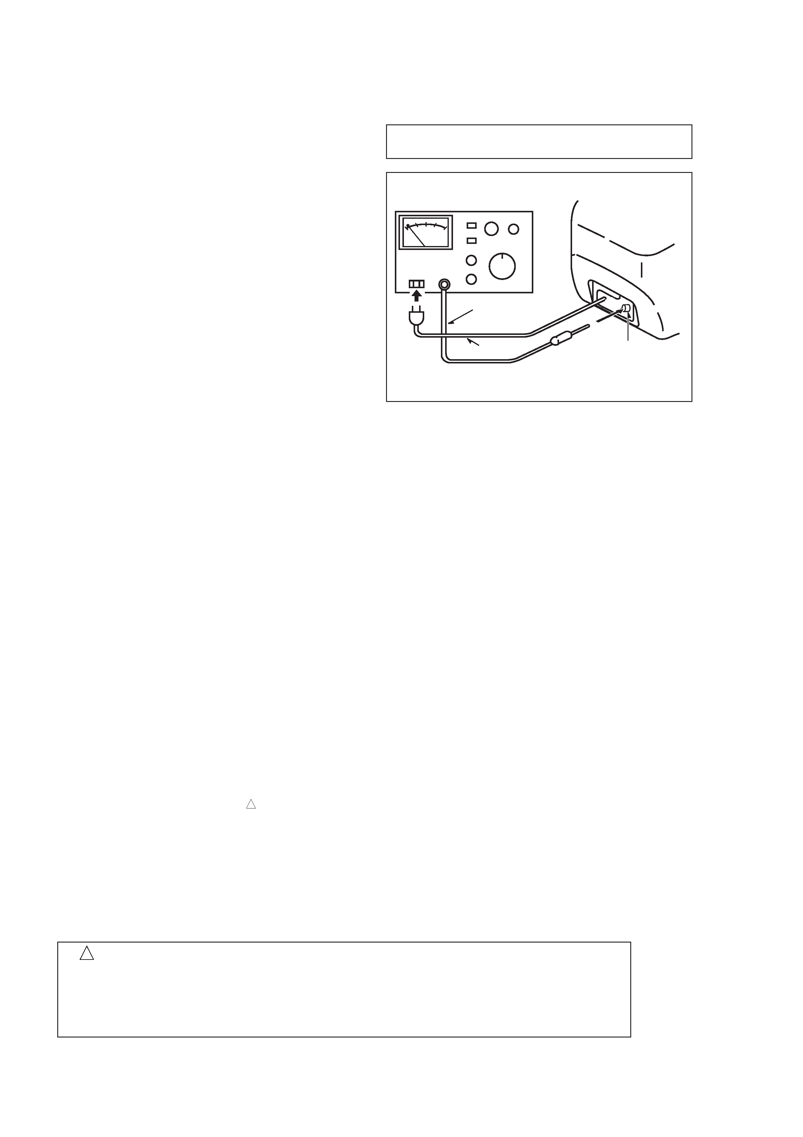
5. After repairing, always measure the insulation
resistance and perform the voltage-withstand test
(See Fig-1).
1) The insulation resistance must be 3.5 to 6.0 M
when applying
500V per second.
2) In the voltage withstand test, apply 1.0 KV for 1
minute and check that the GO lamp lights.
*
Breaking current set to 10 mA.
*
Connect the safety checker as shown in Fig-1,
then measure the resistance and perform the test.
*
Do not touch the equipment during testing.
*
For details of the safety checker, refer to the supplied
Operation manual.
not to get close to the pyrogenic parts and high
voltage parts. Therefore, put these parts in the
original positions.
5. Take care of the cathode-ray tube.
By setting an explosion-proof cathode-ray tube in this
equipment, safety is secured against implosion.
However, when removing it or servicing from the
back, it gives out shock that is dangerous. Take
enough care to deal with it.
6. Avoid an X-ray.
Safety is secured against an X-ray by giving
considerations to the cathode-ray tube and the high
voltage peripheral circuit, etc. Therefore, when
repairing the high voltage peripheral circuit, use the
designated parts and do not change the circuit.
Repairing, except indicates, causes rising of high
voltage, and the cathode-ray tube emits an X-ray.
7. Perform a safety check after servicing.
Confirm that the screws, parts and wiring which were
removed in order to service are put in the original
positions, or whether there are deteriorated portions
around the places serviced.
Fig-1
Insulation resistance: 3.5 to 6.0 M
(500 V/s)
Voltage-withstand: 1.0 KV for 1 minute
1. Keep the notices.
As for the places which need special attentions, they
are indicated with labels or seals on the cabinet,
chassis and parts. Make sure to keep the indications
and notices in the operation manual.
2. Avoid an electric shock.
There is a high voltage part inside. Avoid an electric
shock while the electric current is flowing.
3. Use the designated parts.
The parts in this equipment have the specific
characteristics of incombustibility and withstand
voltage for safety.
Therefore, use a part which has the same character
as the replaced part. Especially as to the important
parts for safety which is indicated in the circuit
diagram or the table of parts with a
mark, the
designated parts must be used.
4. Put parts and wires in the original position after
assembling or wiring.
There are parts which use the insulation material
such as a tube or tape for safety, or which are
assembled so that these parts do not make contact
with the printed board. The inside wiring is designed
!
Safety checker (Model 7110, etc.)
Earth cable
AC cable
Connect the earth cable
to the outside metal part
terminal.
Safety Components Symbol
This symbol is given to important parts which serve to maintain the safety of the product, and which
are made to confirm to special Safety Specifications.
Therefore, when replacing a component with this symbol make absolutely sure that you use a
designated part.
!