SERVICE MANUAL
DA
TA
COLOR TELEVISION
TV-A2115 KE
S/M Code No. 09-008-429-9S1
SUPPLEMENT
· This Service Manual contains the additional information "DISASSEMBLY
INSTRUCTIONS" and "ADJUSTMENT" for the model TV-A2115 (KE).
If requiring the other information, see Service Manual of TV-A2115 (KE),
(S/M Code No. 09-005-429-9R1).
2
Anode cap
CRT GND
Hook
CRT
CRT GND
Grip
DISASSEMBLY INSTRUCTIONS
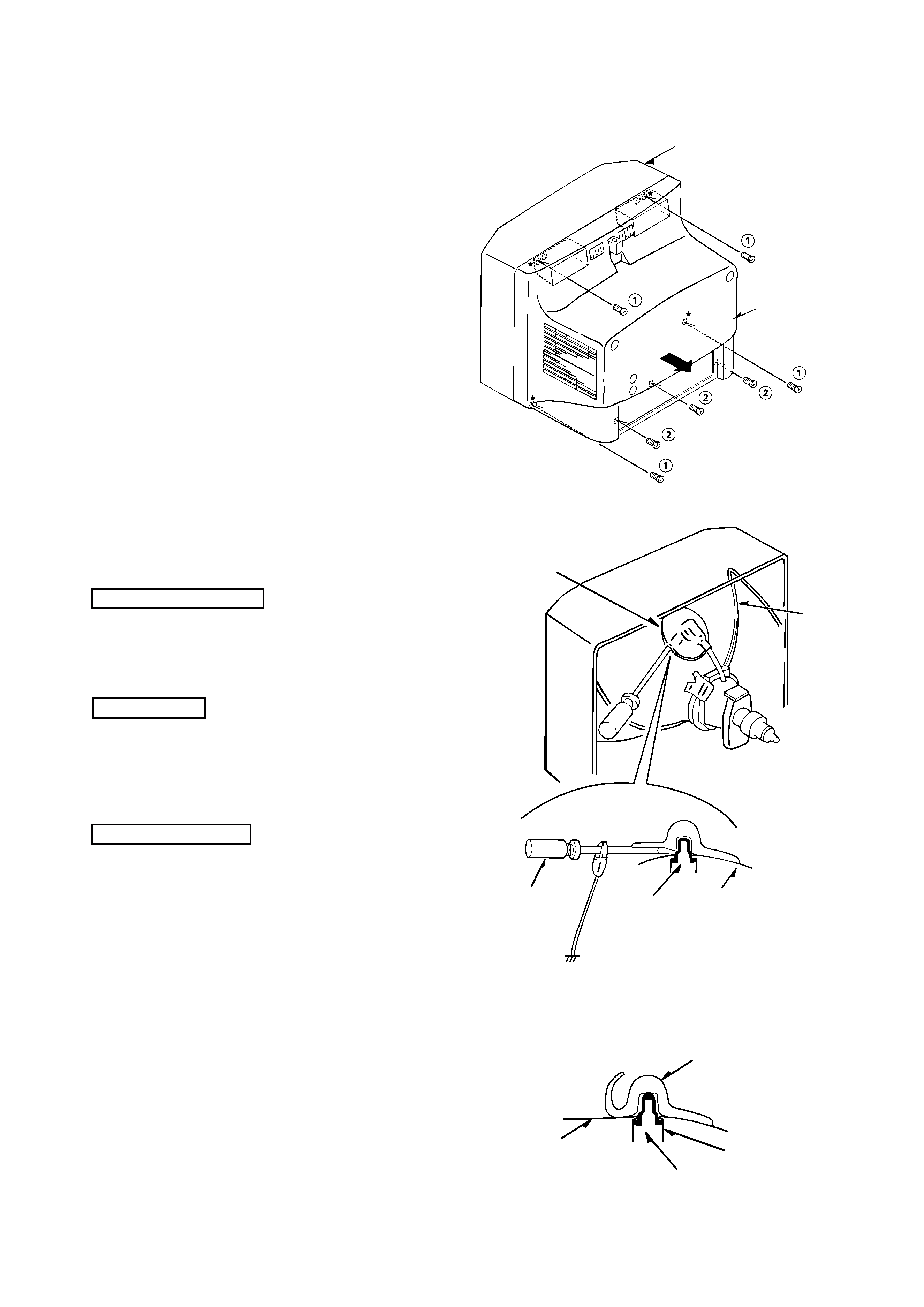
1. REAR CABINET REMOVAL
Figure 1-1
2. HIGH-VOLTAGE CAP (ANODE CAP) REMOVAL
2-1. Cautions before Removing
Discharge the anode voltage
(1)
The anode voltage is not discharged completely from the
CRT of this unit even after the power is turned off. Be
sure to discharge the residual anode voltage before
removing the anode cap.
Do not use pliers
(2)
Do not use pliers, etc. to remove the anode cap. If you
used pliers and bent the hook to remove the cap, the spring
characteristics of the hook could be lost, and when
reinstalled, the cap would come off from the CRT anode
button easily, causing an accident.
Do not turn the anode cap
(3)
If the anode cap is turned in the direction of its
circumference, the hook is likely to come off.
2-2. Anode Cap Removal
Discharge the anode voltage. (See Figure 2-1)
(1)
Connect a flat-bladed screwdriver to the CRT GND via
an alligator clip.
(2)
Use a tester to check the end of the screwdriver and ground
of the TV for continuity.
(3)
Touch the hook with the end of the screwdriver.
Caution : Be careful not to damage the anode cap.
(4)
Turn over the anode cap.
Caution : Be careful not to damage the anode cap.
Figure 2-1
Figure 2-2
Front cabinet
Rear cabinet
Anode cap
CRT
Hook
Anode button
(1)
Remove four screws 1 and three screws 2 , then remove
the rear cabinet in the direction of the arrow.
(See Figure1-1)
3
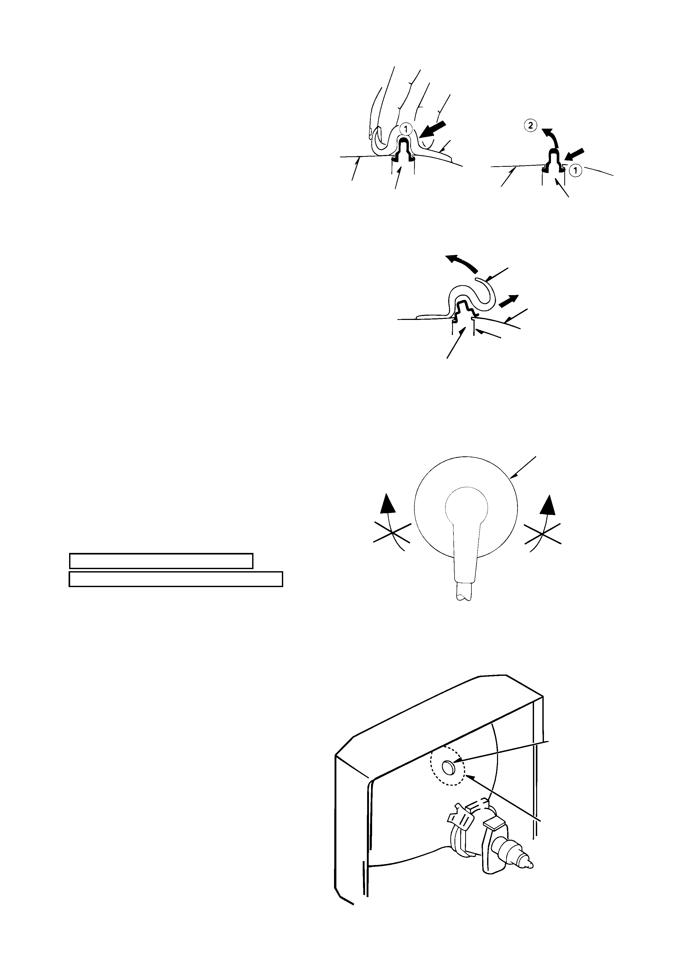
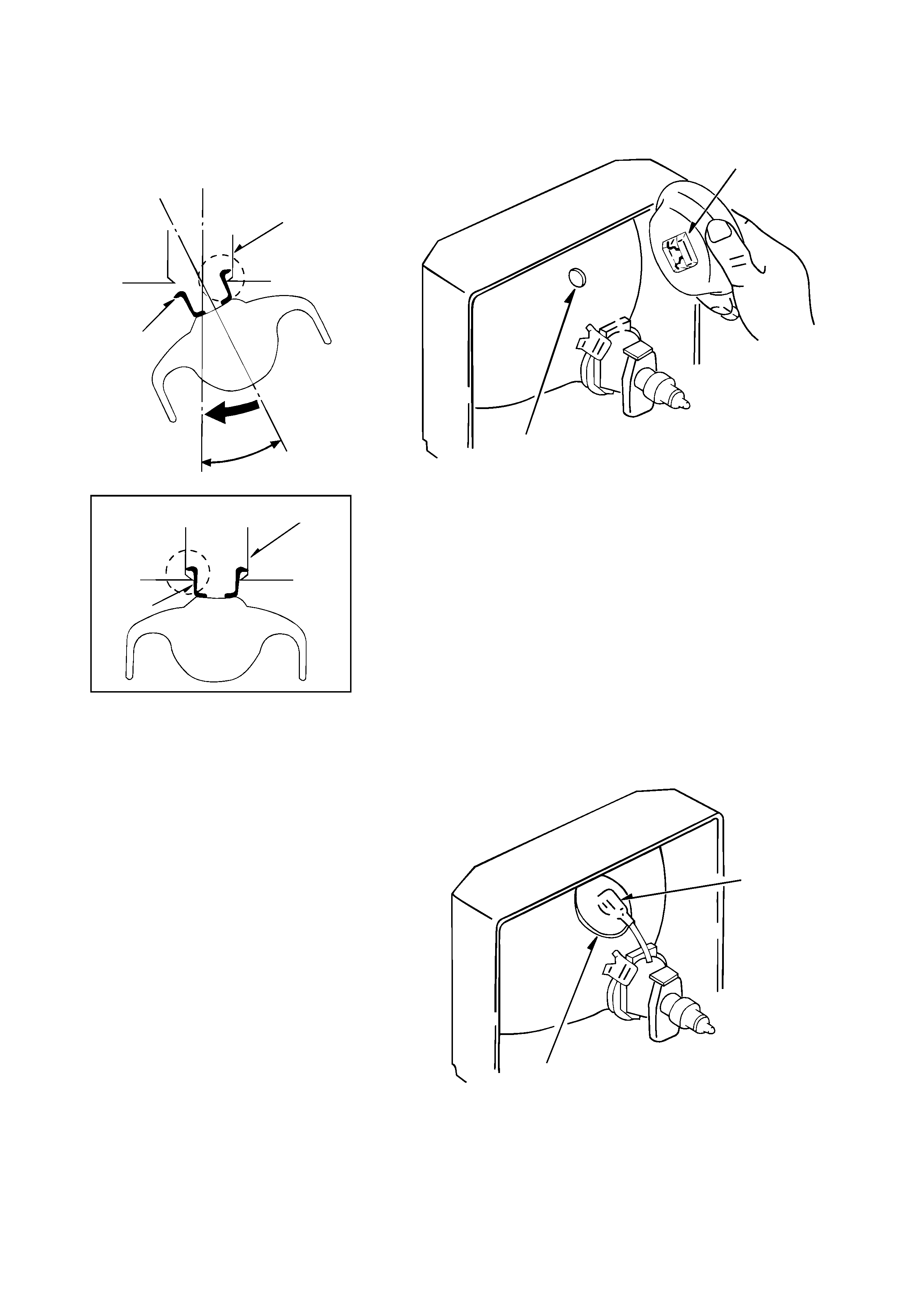
(5)
Push the anode cap with your thumb in the direction of
arrow 1
as shown in the figure, then lift the cap in the
direction of arrow 2
to release the hook on one side.
(See Figure 2-3)
(6)
Turn over the anode cap on the side where the hook was
released and pull out the cap in the direction opposite to
that on which the cap was pushed. (See Figure 2-4)
Caution : Do not pull out the anode cap straight up.
: Do not pull the cap forcibly. After removing
the cap, check that the hook is not deformed.
Figure 2-3
3. ANODE CAP REINSTALLTION
Observe the cautions carefully so that no accident occurs
due to a defect in installing the anode cap and so it does
not come off.
3-1. Caution before Reinstalling
Never turn the anode cap after installing it
Never re-use the hook when it has been deformed
(1)
If the anode cap is turned after it is installed, it may come
off. Therefore, arrange the high-voltage cable before
attaching the anode cap. (See Figure 3-1)
(2)
If you have attached the anode cap before arranging the
high-voltage cable, arrange the cable carefully so the cap
does not turn.
3-2. Anode cap reinstallation
(1)
Use a clean cloth moistened slightly with alcohol to clean
the installation section. (See Figure 3-2)
Caution : Check that the installation section is free from
dust, foreign matter, etc.
(2)
Coat the anode cap installation circumference with an
appropriate amount of the specified silicone grease (KS-
650N).
Caution : Be careful that silicone grease does not enter
the anode button.
CRT
CRT
Anode cap
Hook
Hook
Anode cap
Hook
Anode button
CRT
Left
Right
Anode cap
Anode button
Installation
section
Figure 2-4
Figure 3-1
Figure 3-2
4
(3)
Eliminate twisting, etc. of the high-voltage cable and
arrange it so that no twisting occurs. (See Figure 3-3)
Caution : If the cable is not arranged correctly, the anode
cap could turn and cause an installation defect.
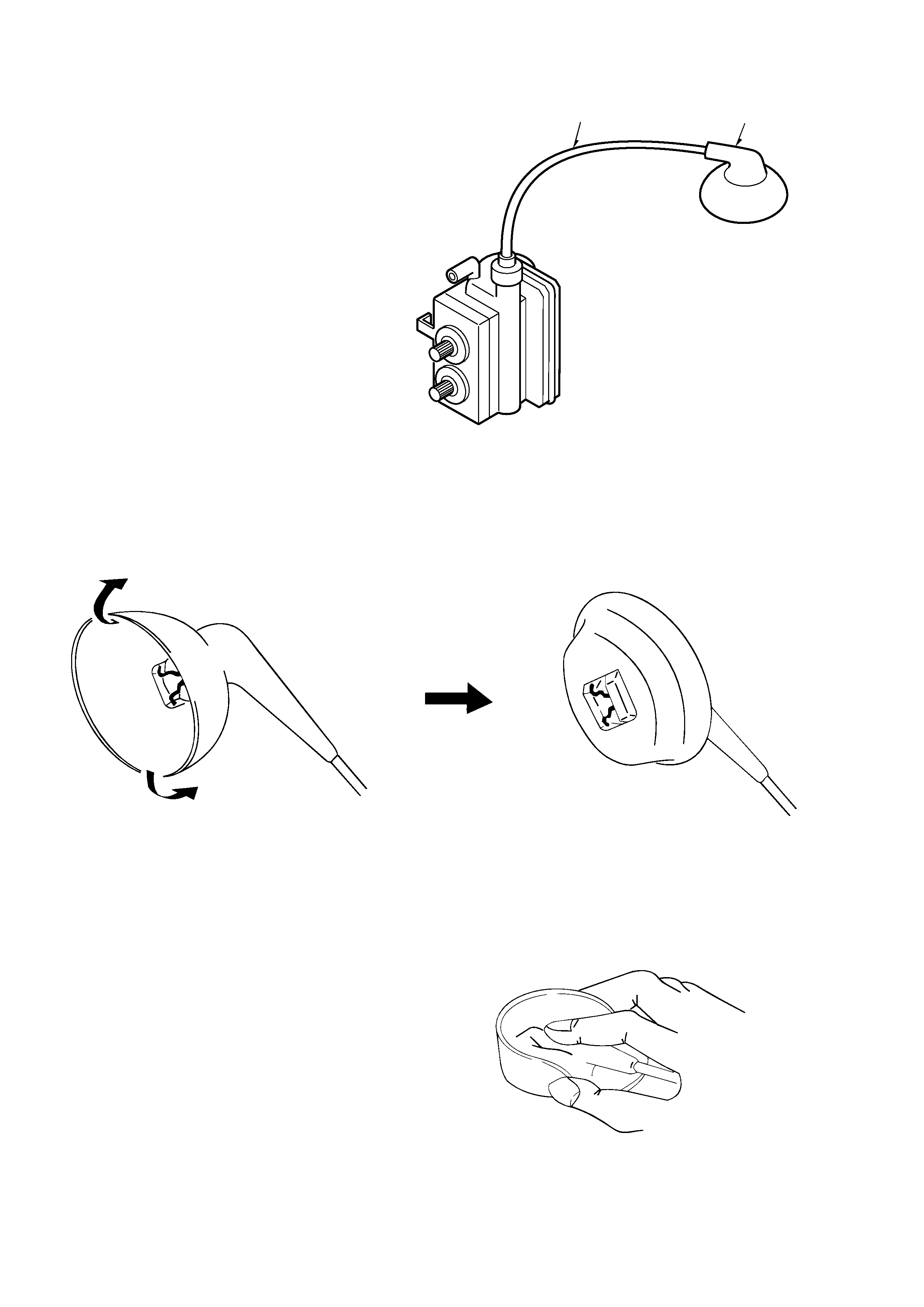
(4)
Turn over the rubber cap symmetrically on the left and
right. (See Figure 3-4)
Caution : Take great care not to damage the anode cap.
Figure 3-3
(5)
Fit your forefinger over the projection at the center of the
cap and hold the cap between your thumb and middle
finger. (See Figure 3-5)
High-voltage cable
Anode cap
Figure 3-4
Figure 3-5
5
(6)
Apply the hook on one side to the anode button as shown
on the figure. (See Figure 3-6)
Caution : Check that the hook is held securely.
(7)
Apply the hook on the other side to the anode button as
shown in Figure 3-7.
(8)
Pull the anode cap slightly with the rubber cap turned
over and visually check that the hook is engaged securely.
(9)
Release your hand from the rubber cap of the anode cap.
Caution : Cover the anode cap so that it does not lift.
(10) Hold the skirt of the andoe cap slightly to improve the
close contact between the cap and CRT.
(11) Check that the anode cap is in close contact with the CRT.
(See Figure 3-8)
Figure 3-8
Figure 3-7
Figure 3-6
Anode button
Skirt
Hook
Anode button
Anode button
Hook
Anode button
Hook
30
°