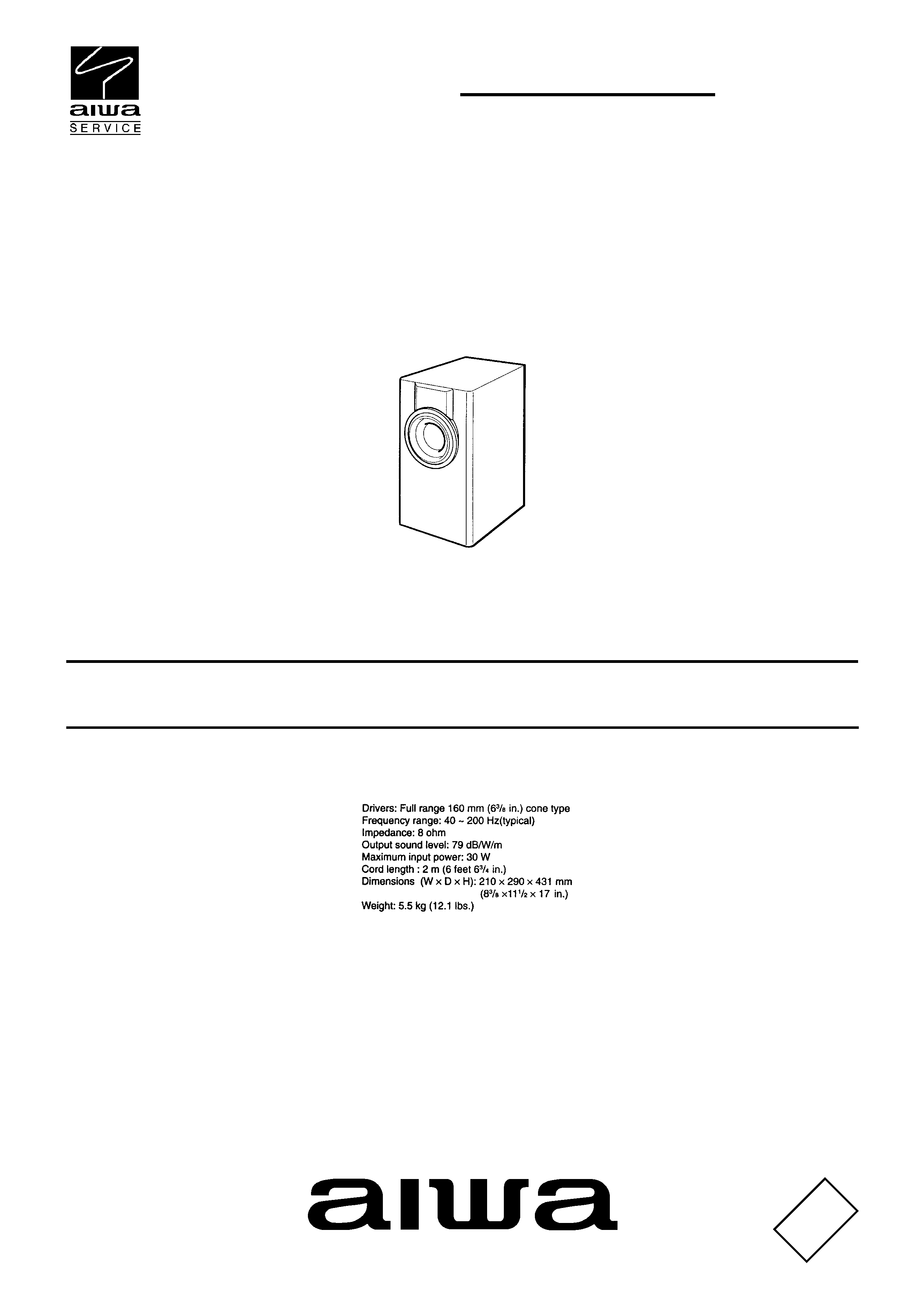
SPEAKER SYSTEM
SX-STV10
S/M Code No. 09-99A-336-3N1
Y
SERVICE MANUAL
DA
TA
SPECIFICATIONS
· Design and specifications are
subject to change without
notice
.
2
1
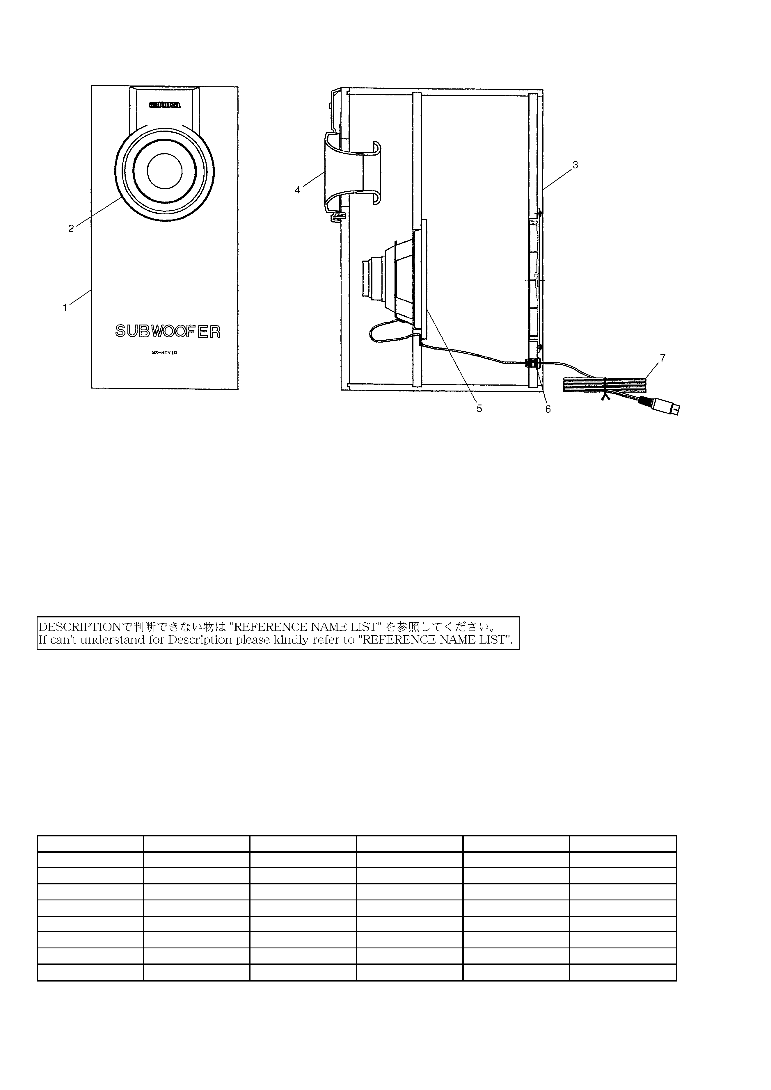
8Z-YS5-005-010
CABI,FR
2
8Z-YS5-001-010
PANEL,FR
3
8Z-YS5-002-010
PANEL,REAR
4
8Z-YS5-003-010
PANEL,DUCT
5
8Z-YS5-601-010
SPKR,W 160 8OHM 75W
6
8Z-NSY-003-010
CORD,BUSH
7
8Z-YS5-602-010
CORD,DIN5PIN
MECHANICAL EXPLODED VIEW 1/1
REF. NO
PART NO.
KANRI
DESCRIPTION
NO.
MECHANICAL PARTS LIST 1/1
Basic color symbol
Color
Basic color symbol
Color
Basic color symbol
Color
B
Black
C
Cream
D
Orange
G
Green
H
Gray
L
Blue
LT
Transparent Blue
N
Gold
P
Pink
R
Red
S
Silver
ST
Titan Silver
T
Brown
V
Violet
W
White
WT
Transparent White
Y
Yellow
YT
Transparent Yellow
LM
Metallic Blue
LL
Light Blue
GT
Transparent Green
LD
Dark Blue
DT
Transparent Orange
COLOR NAME TABLE
3
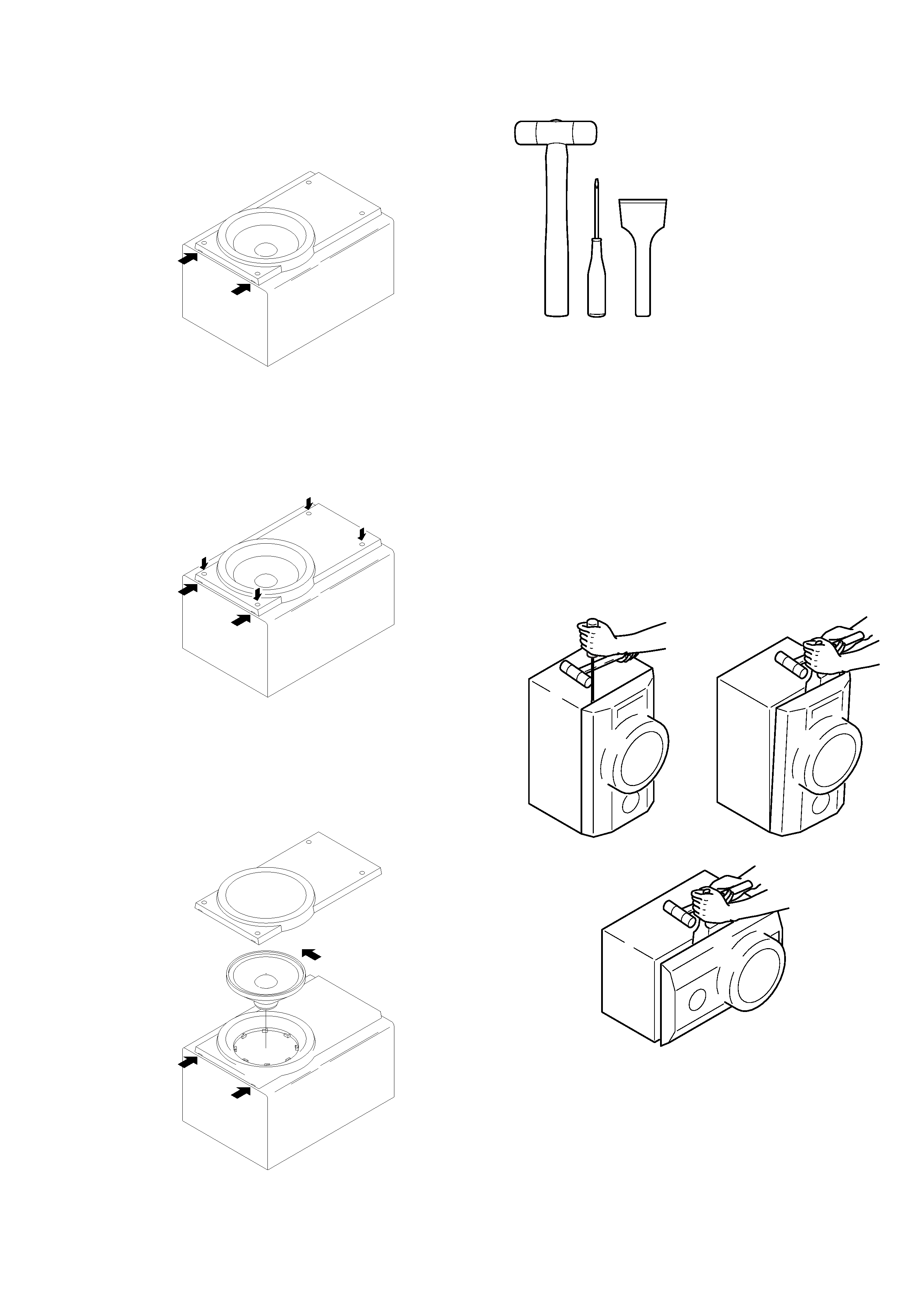
SPEAKER DISASSEMBLY INSTRUCTIONS
Insert a flat-bladed screwdriver into the position indicated by the
arrows and remove the panel. Remove the screws of each speaker
unit andthen remove the speaker units.
Remove the grill frame and four pieces of rubber caps by pulling
out with a flat-bladed screwdriver. Remove the screws from hold
where installed rubber caps. Insert a flat-bladed screwdriver into
the position indicated by the arrows and remove the panel. Re-
move the screws of each speaker unit and then remove the speaker
units.
Insert a flat-bladed screwdriver into the position indicated by the
arrows and remove the panel. Turn the speaker unit to counter-
clockwise direction while inserting a flat-bladed screwdriver into
one of the hollows arround speaker unit, and then remove the speaker
unit. After replacing the speaker unit, install it turnning to clock-
wise direction unitil "click" sound comes out.
Type.1
Type.3
Type.2
TOOLS
1 Plastic head hammer
2 (-) flat head screwdriver
3 Cut chisel
How to Remove the PANEL, FR
1.
Insert the (-) flat head screwdriver tip into the gap
between the PANEL, FR and the PANEL, SPKR. Tap
the head of the (-) flat head screwdriver with the plastic
hammer head, and create the clearance as shown in Fig-1.
2.
Insert the cut chisel in the clearance, and tap the head of
the cut chisel with plastic hammer as shown in Fig-2, to
remove the PANEL, FR.
3.
Place the speaker horizontally. Tap head of the cut
chisel with plastic hammer as shown in Fig-3, and
remove the PANEL, FR completely.
Type.4
Fig-1
Fig-2
Fig-3
How to Attach the PANEL, FR
Attach the PANEL, FR to the PANEL, SPKR. Tap the four
corners of the PANEL, FR with the plastic hammer to fit the
PANEL, FR into the PANEL, SPKR completely.
1
2
3

920074
Printed in Singapore
211, IKENOHATA 1CHOME, TAITO-KU, TOKYO 110-8710, JAPAN TEL:03 (3827) 3111
1
8Z-YS5-901-010
IB,Y (E,S,R,G,A,PE) BASS
REF. NO
PART NO.
KANRI
DESCRIPTION
NO.
ACCESSORIES/PACKAGE LIST