VIDEO MECHANISM
NC3600 P4LRH
S/M Code No. 09-995-333-1N1
English
SERVICE MANUAL
DA
TA

2
VCR TEST TAPE INTERCHANGEABILITY TABLE
There are two types of the new allgnment tape CH-1B (for NTSC) and CH-2 (for PAL). On each tape four signals (1)-(4)
are recorded for the times and in the order shown below.
(1) : 8min. fi (2) : 2min. fi (3) : 5min. fi (4) : 5min.
The TTV-MP1 (for M-PAL), TTV-MS1 (for MESECAM) and TTV-S1 (for SECAM) allgnment tapes have the same
contents as the previous tapes.
* 1. Described in the order of color format. video signal. linear audio. tape speed and Hi-Fi audio.
* 2. Use CH-1B (1)-(3) with models used exclusively in the SP mode.
* 3. Use CH-2 (3) and (4) when it is necessary to observe the chroma signal.
Method
Now in use TYPE
Model
Contents *1
New TYPE
Model
Contents *1
Application
NTSC
PAL
TTV-N1
NTSC, Color bar,
1kHz, SP
TTV-NS1
NTSC, Color bar,
1kHz, SP
TTV-N1E
NTSC, Color bar,
1kHz, EP
TTV-NS6E
NTSC, Color bar,
No sound, EP
TTV-N2
NTSC, Stairsteps,
7kHz, SP
TTV-N12
(SCV-1998)
NTSC, Color bar,
1kHz, SP
NTSC, Mono scope,
7kHz, SP
TTV-N7A
NTSC, Stairsteps,
1kHz, SP, HiFi 400Hz
TTV-N6
(TTV-N06T)
TTV-P1
PAL, Color bar,
1kHz, SP
TTV-P1L
PAL, Color bar,
1kHz, LP
TTV-P2
PAL, Stairsteps,
6kHz, SP
PAL, Monoscope,
6kHz, SP
TTV-P6
(TTV-N06T)
TTV-P7
PAL, Stairsteps,
1kHz, SP,
HiFi 1kHz
TTV-P16
PAL, Color bar,
400Hz,
SP, HiFi 1kHz
CH-1B(2)
NTSC, Stairsteps,
1kHz, SP
No Changed.
NTSC, Color bar,
1kHz, EP
CH-1B(4)
*2
No Changed.
CH-1B(1)
NTSC, Stairsteps,
7kHz, SP
CH-1B(4)
NTSC, Color bar,
1kHz, EP
No Changed.
CH-1B(3)
NTSC, Color bar,
No sound SP,
HiFi 400Hz
PAL, Stairsteps,
1kHz, SP
CH-2(2)
* 3
CH-2(4)
PAL, Color bar,
1kHz, LP
CH-2(1)
PAL, Stairsteps,
6kHz, SP
No Changed.
CH-2(3)
PAL, Color bar,
No sound
SP, HiFi400Hz
No Changed.
PB-Y Level/General electrical ADJ.
Head ACE Height/Tilt ADJ.
For S-VHS (SQPB) check
Switching position ADJ.
For S-VHS (SQPB) check
Head ACE Azimuth ADJ.
FM Envelope ADJ.
X-Value ADJ.
For total picture quality check (resolution, etc)
HiFi Audio PB Level ADJ.
Switching position ADJ.
PB-Y Level/General electrical ADJ.
Head ACE Height/Tilt ADJ.
Switching position. (LP Model)
FM Envelope ADJ. (LP Model)
X-Value ADJ. (LP Model)
HEAD ACE Azimuth ADJ.
FM Envelope ADJ. (SP Model)
X-Value ADJ. (SP Model)
For total picture quality check (resolution, etc)
FM Filter ADJ.
HiFi Audio PB Level ADJ.
3
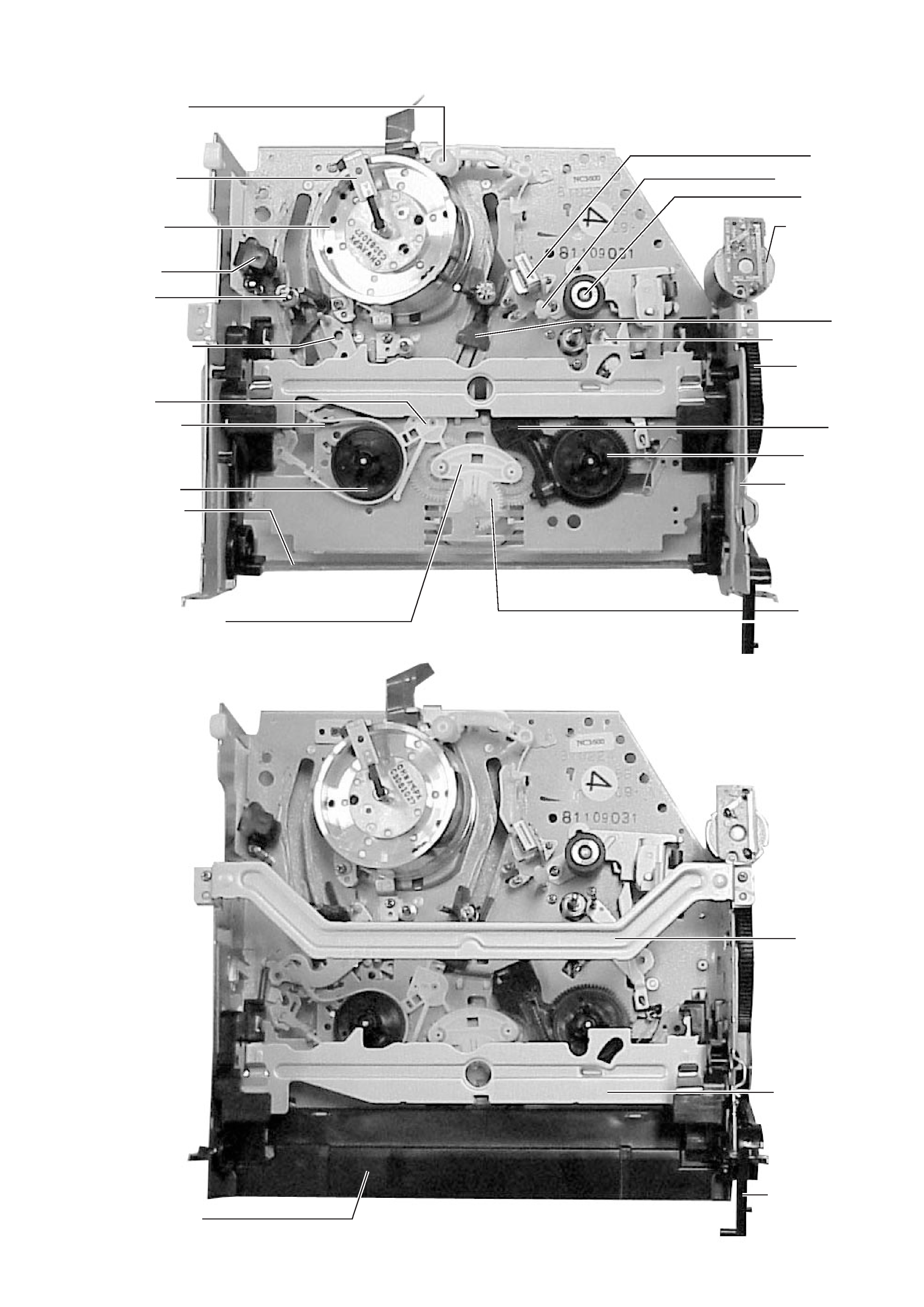
Head cleaner
Drum brush
Center gear
assembly
FE head
S slider
Tension lever
S brake
Band brake
S reel table
FL arm lever
Idle lever assembly
Cylinder
assembly
ACE head
No. 8 guide cap
Pinch roller
Loading motor
T slider
No. 9 guide lever
FL cam gear
T brake
T real table
FL drive slider
Top bracket
Cassette holder
assembly
Door open lever
FL cassette
guide assembly
2-1. LOCATION OF MECHANISM PARTS
Fig-2-1-1 Upper side
Fig-2-1-2 Upper side
2. MECHANICAL ADJUSTMENT
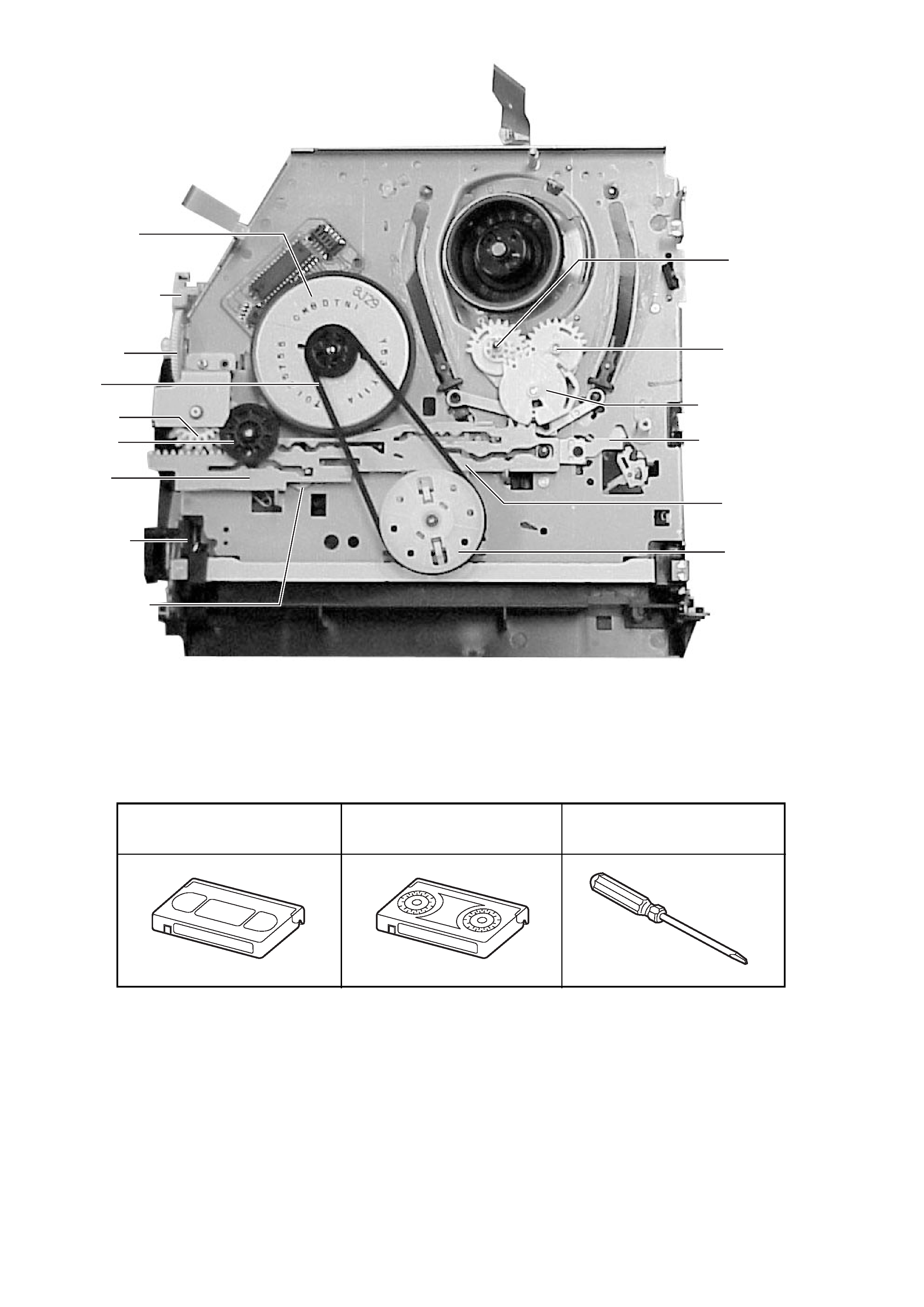
4
Fig-2-1-3 Rear side
2-2. SERVICE TOOL LIST
Capstan motor
Worm gear holder
Worm wheel
Reel belt
Joint gear 1
Joint gear 2
Cam slider
S-VHS switch
Pinch drive lever
T loading lever
assembly
S loading lever
assembly
Loading drive gear
Tension drive lever
Up/down lever
Holder clutch
assembly
Alignment tape
Torque cassette
Post height adjustment screwdriver
(SRK-VHT-103-404)
(SV-TG0-030-000)
5
Remarks
· Cleaning shall be
performed using a
cotton swab or cotton
cloth moistened with
alcohol.
· After cleaning, wait
until the cleaned parts
are dried completely
before using a video
cassette tape.
· Use the specified oil for
lubrication.
· When lubricating a part,
apply only one or two
drops of oil after
cleaning the part with
alcohol.
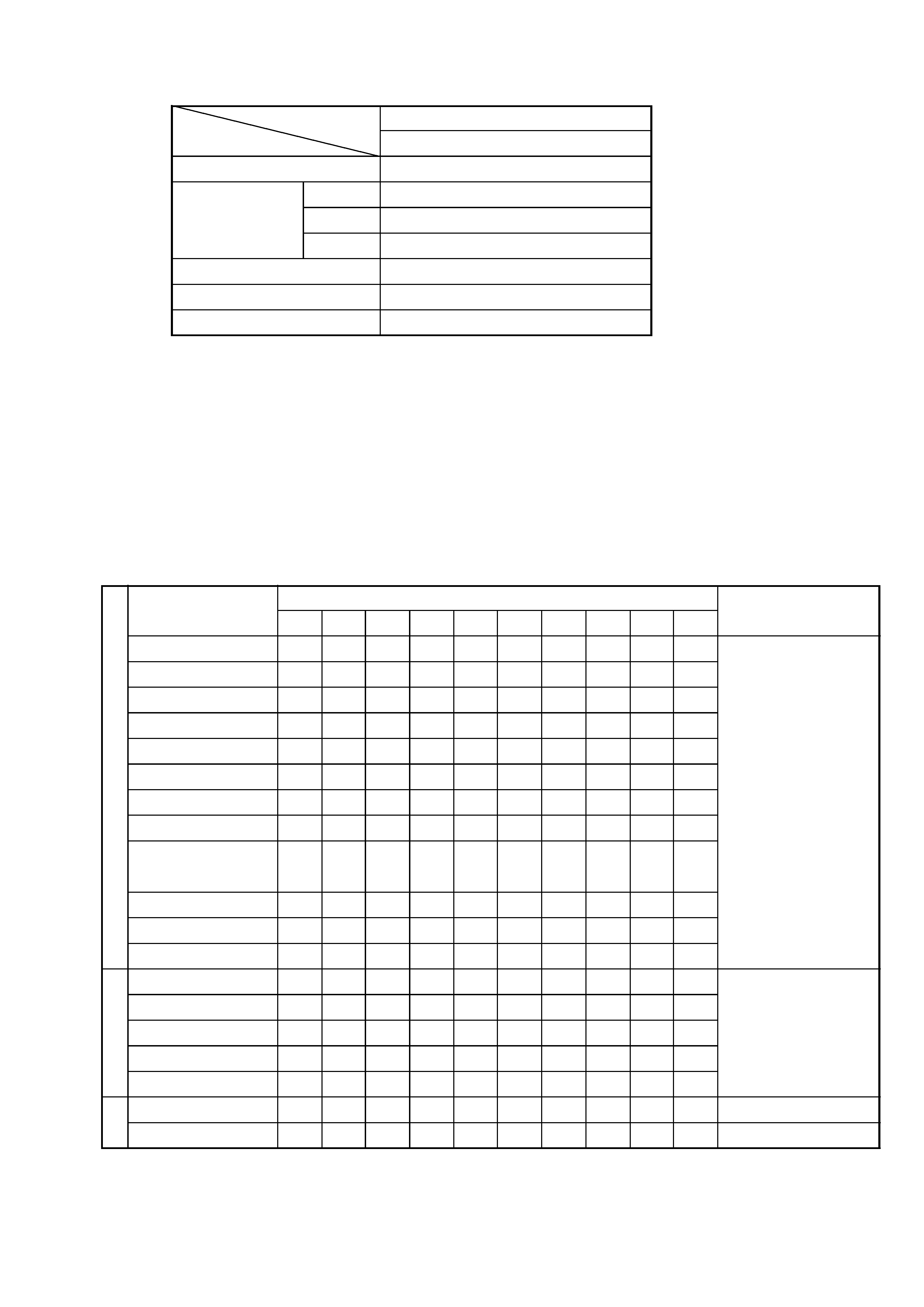
2-3. ALIGNMENT TAPES FOR ADJUSTMENT
2-4. GUIDELINE OF MAJOR PARTS REPLACEMENT
·
The replacement periods that are shown below, indicate the guide line only, and are the life of the individual parts.
·
The following guideline is compiled on the assumption the mechanism is used under the standard operating conditions
(i.e., normal temperature and normal humidity.) The replacement periods change depending on the operating
environments, method of use and running hours.
·
Life of head assembly (cylinder) is especially heavily affected by the operating conditions.
Table 2-4-1
3: Cleaning
0: Check the part. Replace when the part needs replacement.
*: Impedance roller is used in some models, but not used in some other models.
Mechanism
PAL
Adjustment item
SP/LP 2/4 head
FM envelope
TTV-P2L
Slant
Commercially available tape
A/C head
Height
TTV-P1 (TTV-P1L)
Azimuth
TTV-P2
X value
TTV-P2 (TTV-P2L)
RG post slant
Commercially available tape
Tape back-tension
SRK-VHT-103
Tape
run
mechanism
Drive
mechanism
Others
Parts name
Tension post
S/T slant guide post
Impedance roller
Guide post No. 8
Capstan
Guide post No. 9
Guide post No. 3
S/T guide roller
Head assembly
(cylinder)
FE head
ACE head
Pinch roller
Capstan motor
Loading motor
Reel belt
Clutch gear assembly
Idle lever assembly
Band brake
Slip ring assembly
500
3
3
3
3
3
3
3
3
1000
3
3
0
3
0
0
3
0
0
0
0
0
1500
3
3
0
3
0
0
3
0
0
0
0
0
2000
3
0
0
0
0
0
3
0
0
0
0
0
0
2500
3
0
0
0
0
0
3
0
0
0
0
0
0
3000
3
0
0
0
0
0
0
0
0
0
0
0
0
3500
3
0
0
0
0
0
0
0
0
0
0
0
0
4000
3
0
0
0
0
0
0
0
0
0
0
0
0
4500
3
0
0
0
0
0
0
0
0
0
0
0
0
5000
3
0
0
0
0
0
0
0
0
0
0
0
0
Guideline of time