COMPACT DISC STEREO SYSTEM
SISTEMA ESTÉREO DE DISCOS COMPACTOS
CHAINE STEREO AVEC LE LECTEUR DE DISQUE COMPACT
LCX-357
OPERATING INSTRUCTIONS
MANUAL DE INSTRUCCIONES
MODE D'EMPLOI
En (English)
E (Español)
F (Français)
U
8A-CLA-903-01
000105AYK-H-B
For assistance and information,
call toll free 1-800-BUY-AIWA.
(United States and Puerto Rico)
2 ENGLISH
ENGLISH
WARNING
TO REDUCE THE RISK OF FIRE OR ELECTRIC
SHOCK, DO NOT EXPOSE THIS APPLIANCE TO
RAIN OR MOISTURE.
"CAUTION:TO REDUCE THE RISK OF
ELECTRIC SHOCK,
DO NOT REMOVE COVER (OR BACK).
NO USER-SERVICEABLE PARTS INSIDE.
REFER SERVICING TO QUALIFIED
SERVICE PERSONNEL."
CAUTION
RISK OF ELECTRIC SHOCK
DO NOT OPEN
Explanation of Graphical Symbols:
The lightning flash with arrowhead symbol,
within an equilateral triangle, is intended to
alert the user to the presence of uninsulated
"dangerous voltage" within the product's en-
closure that may be of sufficient magnitude to
constitute a risk of electric shock to persons.
The exclamation point within an equilateral
triangle is intended to alert the user to the
presence of important operating and mainte-
nance (servicing) instructions in the literature
accompanying the appliance.
PRECAUTIONS
Read the Operating Instructions carefully and completely before
operating the unit. Be sure to keep the Operating Instructions for
future reference.
All warnings and cautions in the Operating
Instructions and on the unit should be strictly followed, as well as
the safety suggestions below.
Installation
1 Water and moisture Do not use this unit near water, such as
near a bathtub, washbowl, swimming pool, or the like.
2 Heat Do not use this unit near sources of heat, including
heating vents, stoves, or other appliances that generate heat.
It also should not be placed in temperatures less than 5°C
(41°F) or greater than 35°C (95°F).
3 Mounting surface Place the unit on a flat, even surface.
4 Ventilation The unit should be situated with adequate space
around it so that proper heat ventilation is assured. Allow 10 cm
(4 in.) clearance from the rear and the top of the unit, and 5 cm
(2 in.) from each side.
- Do not place the unit on a bed, rug, or similar surface that may
block the ventilation openings.
- Do not install the unit in a bookcase, cabinet, or airtight rack
where ventilation may be impeded.
5 Objects and liquid entry Take care that objects or liquids do
not get inside the unit through the ventilation openings.
6 Carts and stands When placed or
mounted on a stand or cart, the unit
should be moved with care.
Quick stops, excessive force, and un-
even surfaces may cause the unit or
cart to overturn or fall.
7 Condensation Moisture may form on the CD pickup lens
when:
- The unit is moved from a cold spot to a warm spot
- The heating system has just been turned on
- The unit is used in a very humid room
- The unit is cooled by an air conditioner
When this unit has condensation inside, it may not function
normally. Should this occur, leave the unit for a few hours, then
try to operate again.
8 Wall or ceiling mounting The unit should not be mounted on
a wall or ceiling, unless specified in the Operating Instructions.
Electric Power
1 Power sources Connect this unit only to power sources
specified in the Operating Instructions, and as marked on the
unit.
2 Polarization As a safety feature, some units are equipped
with polarized AC power plugs which can only be inserted one
way into a power outlet. If it is difficult or impossible to insert the
AC power plug into an outlet, turn the plug over and try again.
If it still does not easily insert into the outlet, please call a
qualified service technician to service or replace the outlet. To
avoid defeating the safety feature of the polarized plug, do not
force it into a power outlet.
3 AC power cord
- When disconnecting the AC power cord, pull it out by the AC
power plug. Do not pull the cord itself.
- Never handle the AC power plug with wet hands, as this could
result in fire or shock.
- Power cords should be routed to avoid being severely bent,
pinched, or walked upon. Pay particular attention to the cord
from the unit to the power socket.
- Avoid overloading AC outlets and extension cords beyond
their capacity, as this could result in fire or shock.
4 Extension cord To help prevent electric shock, do not use a
polarized AC power plug with an extension cord, receptacle, or
other outlet unless the polarized plug can be completely in-
serted to prevent exposure of the blades of the plug.
5 When not in use Unplug the AC power cord from the AC
outlet if the unit will not be used for several months or more.
When the cord is plugged in, a small amount of current continues
to flow to the unit, even when the power is turned off.
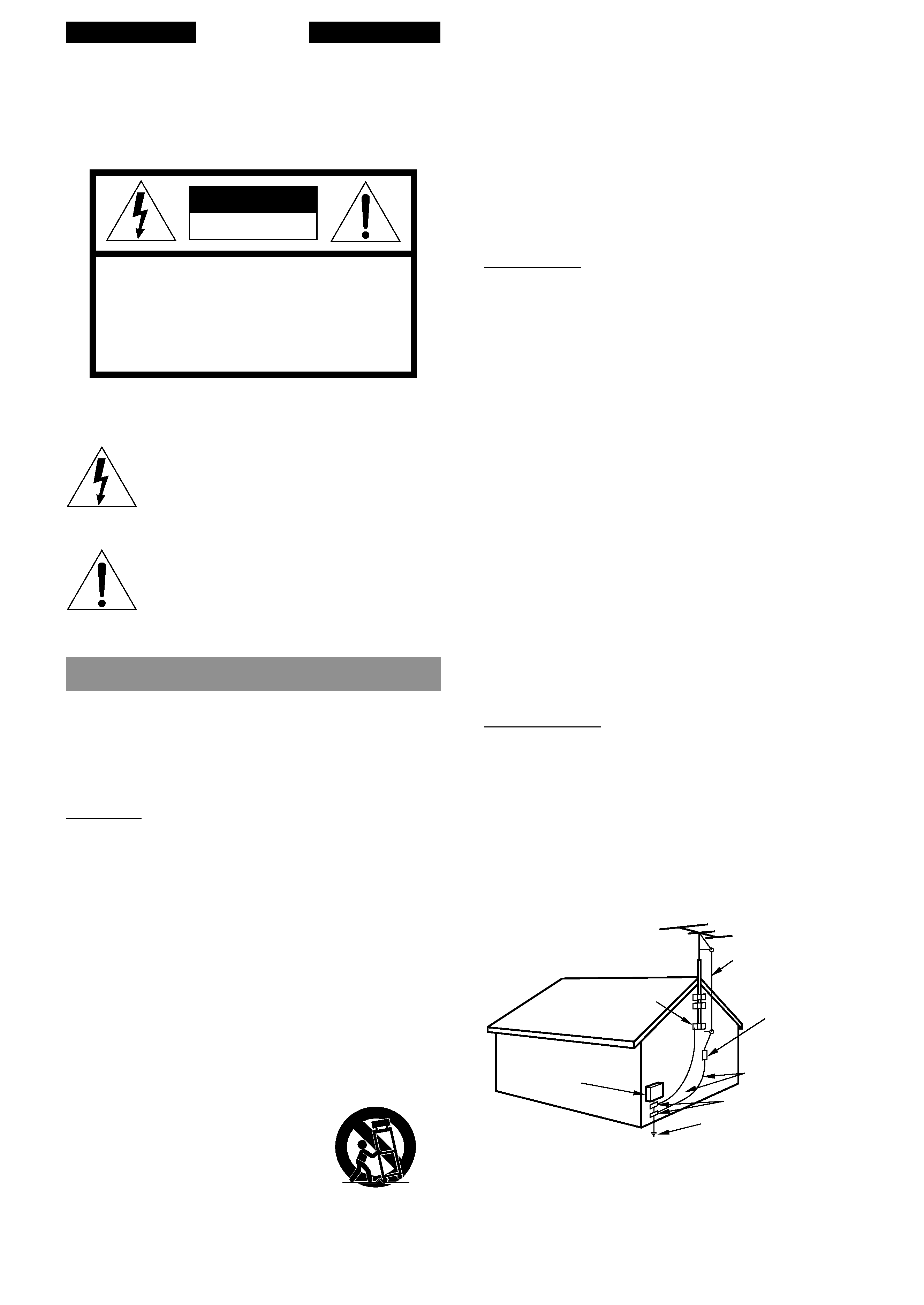
Outdoor Antenna
1 Power lines When connecting an outdoor antenna, make
sure it is located away from power lines.
2 Outdoor antenna grounding Be sure the antenna system is
properly grounded to provide protection against unexpected
voltage surges or static electricity build-up. Article 810 of the
National Electrical Code, ANSI/NFPA 70, provides information
on proper grounding of the mast, supporting structure, and the
lead-in wire to the antenna discharge unit, as well as the size of
the grounding unit, connection to grounding terminals, and
requirements for grounding terminals.
ANTENNA LEAD IN WIRE
ANTENNA DISCHARGE
UNIT
(NEC SECTION 810-20)
GROUNDING
CONDUCTORS
(NEC SECTION 810-21)
GROUND CLAMPS
POWER SERVICE GROUNDING
ELECTRODE SYSTEM
(NEC ART 250 PART H)
NEC-NATIONAL ELECTRICAL CODE
ELECTRIC
SERVICE
EQUIPMENT
GROUND CLAMP
Antenna Grounding According to the National Electrical Code
En
ENGLISH
3
TABLE OF CONTENTS
PRECAUTIONS ................................................................... 2
PREPARATIONS
CONNECTIONS ................................................................. 4
BEFORE OPERATION ........................................................ 6
SETTING THE CLOCK ........................................................ 6
SOUND
ADJUSTING THE SOUND .................................................. 7
RADIO RECEPTION
MANUAL TUNING ............................................................... 8
PRESETTING STATIONS ................................................... 9
CD PLAYING
OPERATION ..................................................................... 10
TAPE PLAYBACK
OPERATION ..................................................................... 12
RECORDING
BASIC RECORDING ........................................................ 13
AI EDIT RECORDING ...................................................... 14
PROGRAMMED EDIT RECORDING ............................... 15
TIMER
TIMER PLAYBACK AND TIMER RECORDING .............. 16
SLEEP TIMER .................................................................. 17
OTHER CONNECTIONS
CONNECTING OPTIONAL EQUIPMENT ....................... 18
LISTENING TO EXTERNAL SOURCES ......................... 18
GENERAL
CARE AND MAINTENANCE ........................................... 19
TROUBLESHOOTING ..................................................... 19
SPECIFICATIONS ............................................................ 20
PARTS INDEX .................................................................. 21
Maintenance
Clean the unit only as recommended in the Operating Instructions.
Damage Requiring Service
Have the units serviced by a qualified service technician if:
- The AC power cord or plug has been damaged
- Foreign objects or liquid have gotten inside the unit
- The unit has been exposed to rain or water
- The unit does not seem to operate normally
- The unit exhibits a marked change in performance
- The unit has been dropped, or the cabinet has been damaged
DO NOT ATTEMPT TO SERVICE THE UNIT YOURSELF.
Owner's record
For your convenience, record the model number and serial number
(you will find them on the rear of your set) in the space provided
below. Please refer to them when you contact your Aiwa dealer in
case of difficulty.
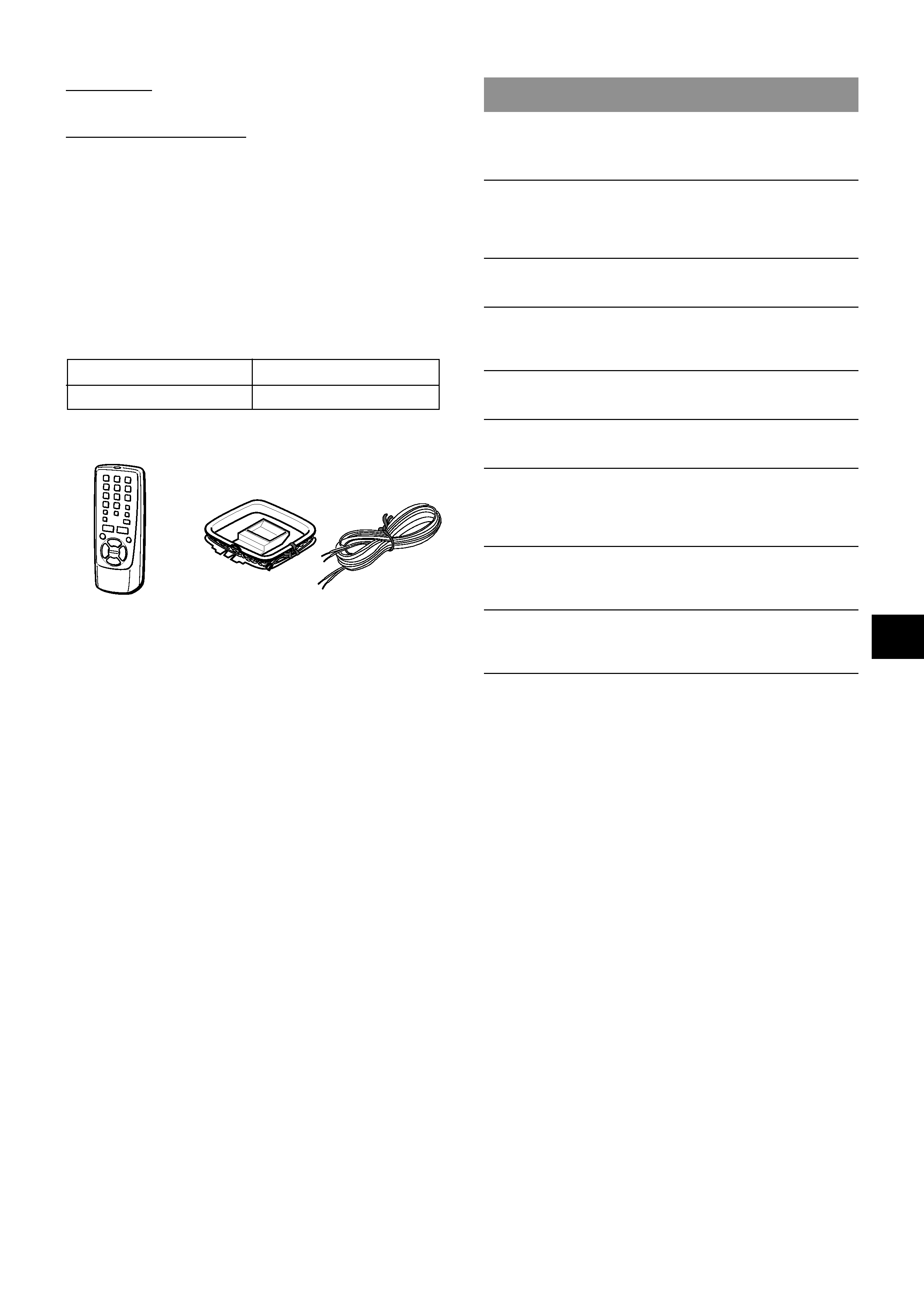
Check your accessories
Operating Instructions, etc.
Model No.
Serial No. (Lot No.)
LCX-357U
FM antenna
AM loop antenna
Remote control
4 ENGLISH
2
1
3
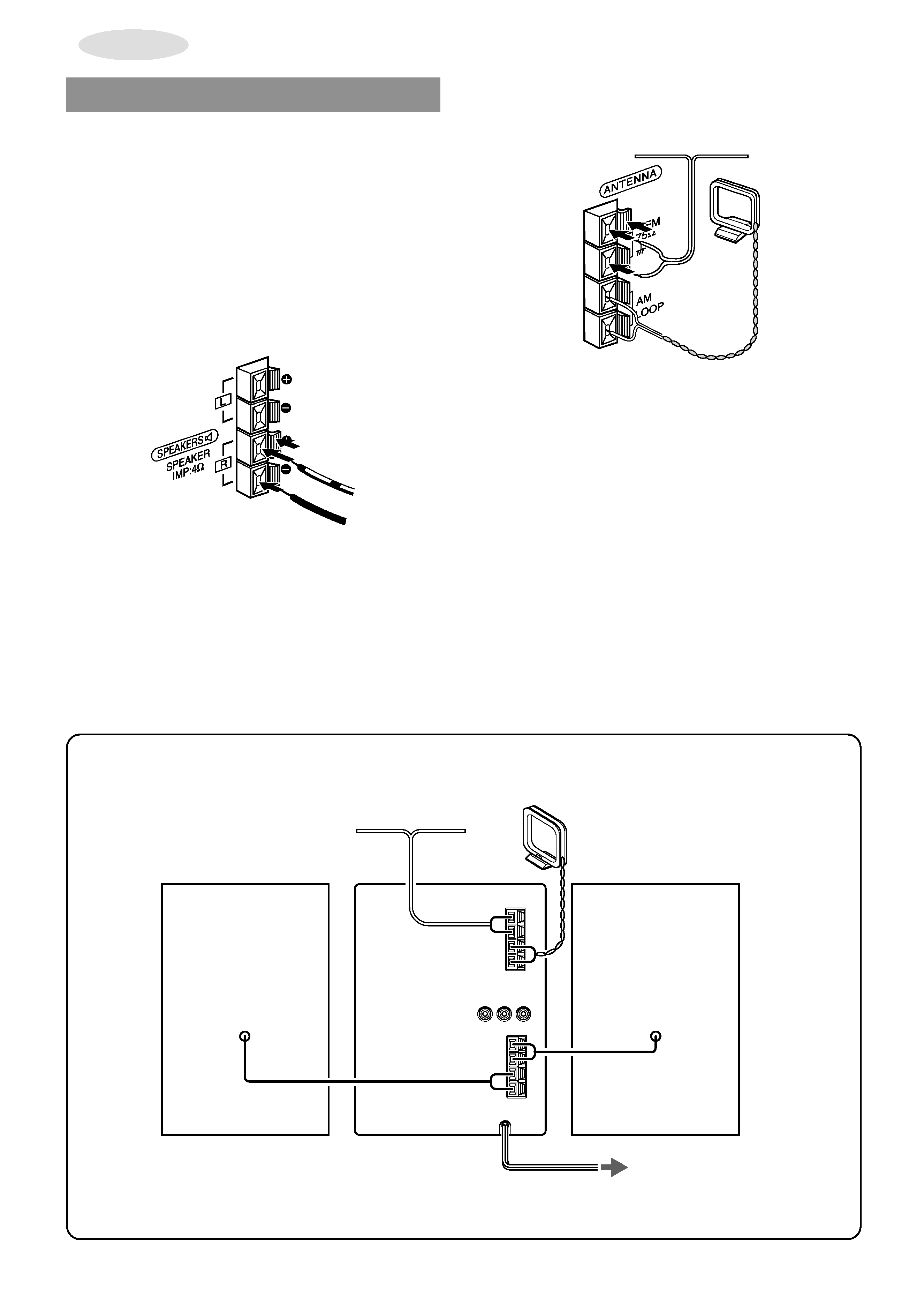
PREPARATIONS
2 Connect the supplied antennas.
Connect the FM antenna to the FM 75
terminals and the
AM loop antenna to the AM LOOP terminals.
3 Connect the AC cord to an AC outlet.
The clock will flash on the display when the AC cord is plugged
into an AC outlet for the first time after purchase.
For setting the clock, see page 6.
CONNECTIONS
Before connecting the AC cord
The rated voltage of your unit shown on the rear panel is 120 V
AC. Check that the rated voltage matches your local voltage.
IMPORTANT
· Connect the speakers, antennas, and all optional equipment
first. Finally, connect the AC cord.
· There are no differences between the front speakers. Both
speakers can be connected as L (Left) or R (Right).
1 Connect the speaker cords to the main unit.
The cords with the white stripes should be connected to the
0 terminals and the other cords to the 9 terminals.
AM loop antenna
FM antenna
Right speaker
Left speaker
AC cord
Speaker
cord
to an AC outlet
AM loop antenna
FM antenna
En
ENGLISH
5
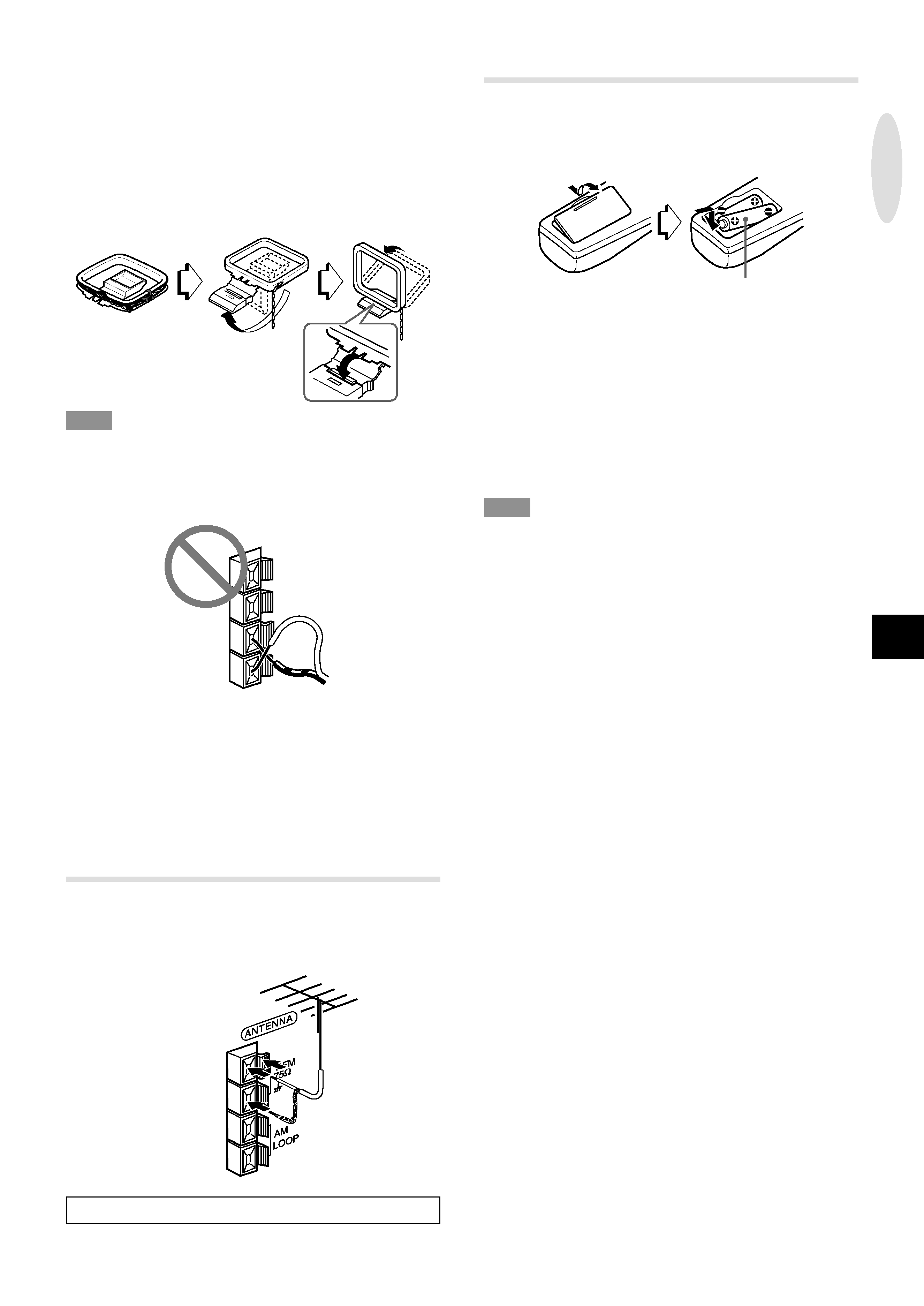
To position the antennas
FM feeder antenna:
Extend this antenna horizontally in a T-shape and fix its ends to
the wall.
AM loop antenna:
Position for the best reception.
To stand the AM loop antenna on a surface
Fix the claw to the slot.
NOTE
· Do not short-circuit the
0 and 9 speaker cord leads, otherwise
the sound may become inaudible or the unit may be turned off.
If this happens, disconnect the AC cord from the AC outlet and
re-connect the speaker cord correctly. Then connect the AC
cord and turn the unit on again.
· Do not connect any speakers to the unit other than the supplied
ones.
· Do not leave objects generating magnetism near the speakers,
as these objects may be damaged.
· Do not bring the FM antenna near metal objects or curtain rails.
· Do not bring the AM loop antenna near other optional
equipment, the stereo system itself, the AC cord or speaker
cords, since noise will be picked up.
· Do not unwind the AM loop antenna wire.
CONNECTING AN OUTDOOR ANTENNA
For better FM reception, use of an outdoor antenna is
recommended.
Connect the outdoor antenna to FM 75
terminals.
To connect other optional equipment © page 18.
PREP
ARA
TIONS
REMOTE CONTROL
Inserting batteries
Detach the battery cover on the rear of the remote control and
insert two size AA (R6) batteries.
R6(AA)
When to replace the batteries
The maximum operational distance between the remote control
and the sensor on the main unit should be approximately 5 meters
(16 feet). When this distance decreases, replace the batteries
with new ones.
Using the FUNCTION button
The FUNCTION button substitutes for the function buttons (TAPE/
REV MODE, TUNER/BAND, CD, AUX) on the main unit.
Each time FUNCTION is pressed, the next function is selected
cyclically.
NOTE
·
c on the remote control has the same function as d on the
main unit.
· If the unit is not going to be used for an extended period of
time, remove the batteries to prevent possible electrolyte
leakage.
· The remote control may not operate correctly when:
The line of sight between the remote control and the remote
sensor is exposed to intense light, such as direct sunlight
Other remote controls are used nearby (television, etc.)