SERVICE MANUAL
DA
TA
BASIC TAPE MECHANISM : OVD-6S
STEREO VIDEO CASSETTE RECORDER
HV-FX8100
S/M Code No. 09-004-344-7N1
U
120V AC, 60Hz
12W
TYP 2.5W (standby mode)
3.2kg (7.1lbs.)
360mm (W) x 232.5mm (D) x 94mm(H)
(14 1/4 x 13 1/8 x 3 3/4 in.)
5°C to 40°C
Rotary 2 head helical scanning system
NTSC color system, 525 lines, 60 fields
Double azimuth 4 heads
VHS video cassette
VHF: 2 to 13
UHF: 14 to 69
CATV: 5A, A-5 to A-1, A to W,
W+1 to W-84
VHF channel 3 or 4 (switchable),
66dBµ
230 lines (at SP)
Frequency synthesized tuner
M
Approx.110 seconds with T-120 tape
More than 90dB (at SP)
SPECIFICATIONS
SP: 33.35 mm/sec
LP: 16.67 mm/sec
SLP: 11.12 mm/sec
SP: 3.5 hours with T-210 tape
LP: 7 hours with T-210 tape
SLP: 10.5 hours with T-210 tape
1.0Vp-p, 75ohm, unbalanced
1.0Vp-p, 75ohm, unbalanced
50dB (nominal)
8dBs, 50K ohm
8dBs, less than 1K ohm
3 tracks (Hi-Fi sound 2 tracks,
Normal sound 1 track)
Normal: 100Hz-10kHz (at SP)
Hi-Fi: 20Hz-20kHz (at SP)
Normal: more than 42 dB (at SP)
TAPE SPEED ......................................
RECORDING/PLAYBACK TIME ........
VIDEO INPUT ......................................
VIDEO OUTPUT .................................
VIDEO S/N ..........................................
AUDIO INPUT .....................................
AUDIO OUTPUT .................................
AUDIO TRACK ....................................
AUDIO FREQUENCY RESPONSE ....
AUDIO S/N ..........................................
POWER REQUIREMENTS .................
POWER CONSUMPTION ...................
WEIGHT ..............................................
DIMENSIONS ......................................
OPERATING TEMPERATURE ...........
VIDEO RECORDING SYSTEM ..........
VIDEO SIGNAL SYSTEM ...................
VIDEO HEAD ......................................
USABLE CASSETTES ........................
CHANNEL COVERAGE ......................
RF OUTPUT ........................................
HORIZONTAL RESOLUTION ............
TUNER SYSTEM ................................
TV SYSTEM ........................................
FAST-FORWARD/REWIND TIME ......
HI-FI DYNAMIC RANGE .....................
Design and specifications are subject to change without
notice.
·

TABLE OF CONTENTS
SPECIFICATIONS ..............................................................................................................................................................
TABLE OF CONTENTS .....................................................................................................................................................
SERVICING NOTICES ON CHECKING .............................................................................................................................
IMPORTANT NOTICE ........................................................................................................................................................
DISASSEMBLY INSTRUCTIONS
REMOVAL OF MECHANICAL PARTS AND P.C. BOARDS ...........................................................................................
REMOVAL OF DECK PARTS ..........................................................................................................................................
KEY TO ABBREVIATIONS .................................................................................................................................................
SERVICE MODE LIST .......................................................................................................................................................
PREVENTIVE CHECKS AND SERVICE INTERVALS .......................................................................................................
NOTE FOR THE REPLACING OF MEMORY IC ................................................................................................................
SERVICING FIXTURES AND TOOLS ................................................................................................................................
PREPARATION FOR SERVICING .....................................................................................................................................
VCR TEST TAPE INTERCHANGEABILITY TABLE ...........................................................................................................
MECHANICAL ADJUSTMENTS
CONFIRMATION AND ADJUSTMENT ............................................................................................................................
CONFIRMATION AND ADJUSTMENT OF TAPE RUNNING MECHANISM ..................................................................
MECHANISM ADJUSTMENT PARTS LOCATION GUIDE .............................................................................................
ELECTRICAL ADJUSTMENTS
BASIC ADJUSTMENTS ...................................................................................................................................................
ELECTRICAL ADJUSTMENT PARTS LOCATION GUIDE .............................................................................................
TROUBLESHOOTING GUIDES ..........................................................................................................................................
IC DESCRIPTIONS ............................................................................................................................................................
SERVO TIMING CHART ....................................................................................................................................................
SYSTEM SWITCH MODE ...................................................................................................................................................
SEMICONDUCTOR BASE CONNECTIONS ......................................................................................................................
BLOCK DIAGRAMS
Y/C/AUDIO/CCD/HEAD AMP ..........................................................................................................................................
TUNER ............................................................................................................................................................................
SYSTEM CONTROL .......................................................................................................................................................
HIFI/DEMODULATOR .....................................................................................................................................................
DISPLAY/OPERATION ...................................................................................................................................................
POWER ...........................................................................................................................................................................
DECK SCHEMATIC DIAGRAM ...........................................................................................................................................
OPERATION SCHEMATIC DIAGRAM ...............................................................................................................................
PRINTED CIRCUIT BOARDS (OPERATION1/2/DECK) ....................................................................................................
PRINTED CIRCUIT BOARDS (SYSCON) ..........................................................................................................................
Y/C/AUDIO/CCD/HEAD AMP SCHEMATIC DIAGRAM .....................................................................................................
SYSTEM CONTROL SCHEMATIC DIAGRAM ...................................................................................................................
TUNER SCHEMATIC DIAGRAM ........................................................................................................................................
HIFI/DEMODULATOR SCHEMATIC DIAGRAM ................................................................................................................
POWER SCHEMATIC DIAGRAM .......................................................................................................................................
DISPLAY SCHEMATIC DIAGRAM .....................................................................................................................................
INTERCONNECTION DIAGRAM ........................................................................................................................................
WAVEFORMS ....................................................................................................................................................................
MECHANICAL EXPLODED VIEW ......................................................................................................................................
MECHANICAL REPLACEMENT PARTS LIST ...................................................................................................................
ACCESSORY REPLACEMENT PARTS LIST ....................................................................................................................
CHASSIS EXPLODED VIEW (TOP VIEW) .........................................................................................................................
CHASSIS EXPLODED VIEW (BOTTOM VIEW) .................................................................................................................
CHASSIS REPLACEMENT PARTS LIST ...........................................................................................................................
ELECTRICAL REPLACEMENT PARTS LIST ....................................................................................................................
A1-1
COVER
A1-1
A2-1
A2-1
B1-1
B2-1~B2-5
C1-1, C1-2
C2-1
C3-1, C3-2
C4-1
C5-1
C5-1
C6-1
D1-1, D1-2
D1-2, D1-3
D1-4
D2-1
D2-2
E-1~E-28
F1-1~F1-3
F2-1
F2-2
G-1, G-2
H-1
H-2
H-3
H-4
H-5
H-6
I-1
I-2
I-3
I-4~I-6
I-7
I-8
I-9
I-10
I-11
I-12
I-13
J-1
K1-1
K1-2
K1-2
K2-1
K2-2
K2-3
K3-1, K3-2

SERVICING NOTICES ON CHECKING
1. KEEP THE NOTICES
As for the places which need special attentions, they are
indicated with the labels or seals on the cabinet, chassis
and parts. Make sure to keep the indications and notices
in the operation manual.
2. USE THE DESIGNATED PARTS
The parts in this equipment have the specific
characters of incombustibility and withstand voltage for
safety. Therefore, the part which is replaced should be
used the part which has the same character.
Especially as to the important parts for safety which is
indicated in the circuit diagram or the table of parts as
a
mark, the designated parts must be used.
3. PUT PARTS AND WIRES IN THE ORIGINAL
POSITION AFTER ASSEMBLING OR WIRING
There are parts which use the insulation material such
as a tube or tape for safety, or which are assembled in
the condition that these do not contact with the printed
board. The inside wiring is designed not to get closer to
the pyrogenic parts and high voltage parts. Therefore,
put these parts in the original positions.
PERFORM A SAFETY CHECK AFTER
SERVICING
4.
Confirm that the screws, parts and wiring which were
removed in order to service are put in the original
positions, or whether there are the portions which are
deteriorated around the serviced places serviced or not.
Check the insulation between the antenna terminal or
external metal and the AC cord plug blades. And be sure
the safety of that.
A2-1
DISASSEMBLY INSTRUCTIONS
1. REMOVAL OF MECHANICAL PARTS
AND P.C. BOARDS
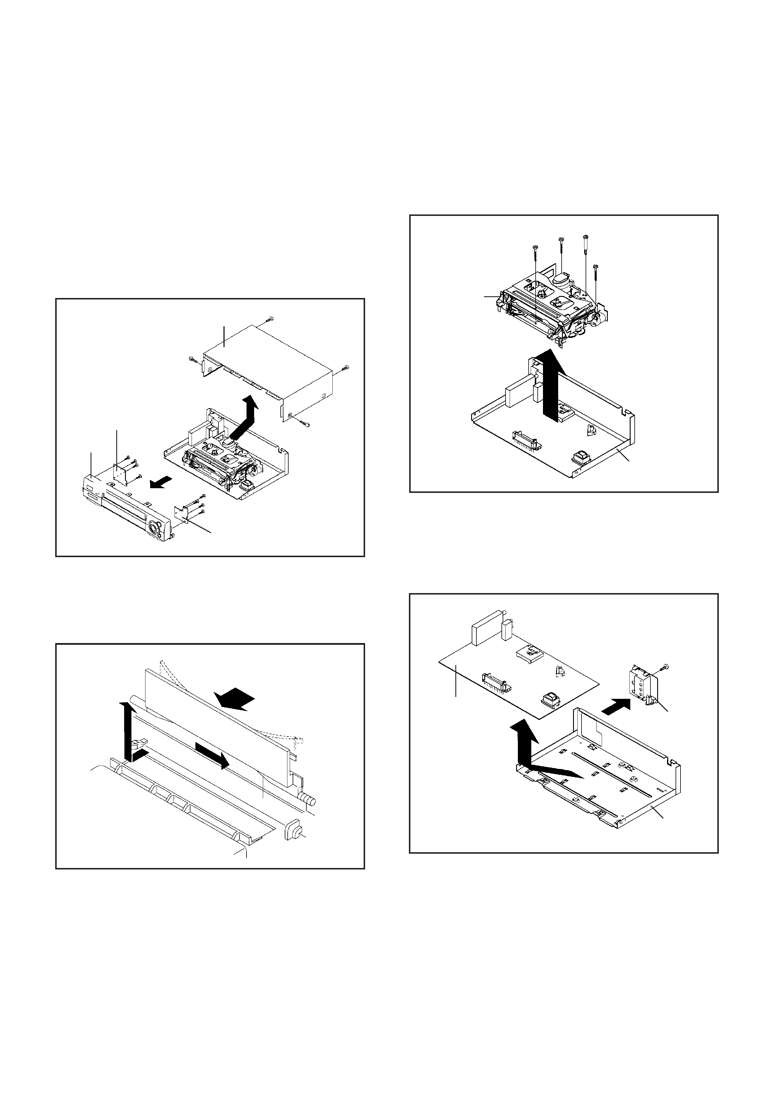
1-1: TOP CABINET, FRONT CABINET AND
OPERATION PCB (Refer to Fig. 1-1)
1.
2.
3.
4.
5.
6.
7.
Remove the 4 screws 1.
Remove the Top Cabinet in the direction of arrow (A).
Disconnect the following connectors: (CP651 and CP652).
Unlock the 7 supports 2.
Remove the Front Cabinet in the direction of arrow (B).
Remove the 4 screws 3 and remove the Operation 1 PCB.
Remove the 4 screws 3 and remove the Operation 2 PCB.
1-3: DECK CHASSIS (Refer to Fig. 1-3)
Remove the 3 screws 1.
Remove the screw 2.
Disconnect the following connectors: (CP1001, CP1002,
CP1003, CP4001, CP4002 and CP4003).
Remove the Deck Chassis in the direction of arrow.
1.
2.
3.
4.
Bottom Plate
Deck Chassis
1-4: SYSCON PCB AND JACK PLATE (Refer to Fig. 1-4)
Remove the screw 1.
Remove the Syscon PCB in the direction of arrow (A).
Unlock the 2 supports 2.
Remove the Jack Plate in the direction of arrow (B).
1.
2.
3.
4.
Fig. 1-3
1
2
1
1
B1-1
1-2: FLAP (Refer to Fig. 1-2)
1.
2.
Open Flap to 90° and flex in direction of arrow (A), at
the same time slide in direction of arrow (B).
Then lift in direction of arrow (C).
(A)
(C)
(B)
Flap
Fig. 1-2
1
1
1
1
(A)
2
2
4
4
4
4
(B)
3
3
3
3
2
2
2
2
2
Operation 2 PCB
Operation 1 PCB
Top Cabinet
Front Cabinet
Fig. 1-1
Fig. 1-4
Syscon PCB
(A)
Jack Plate
(B)
Bottom Plate
1
2
2
DISASSEMBLY INSTRUCTIONS
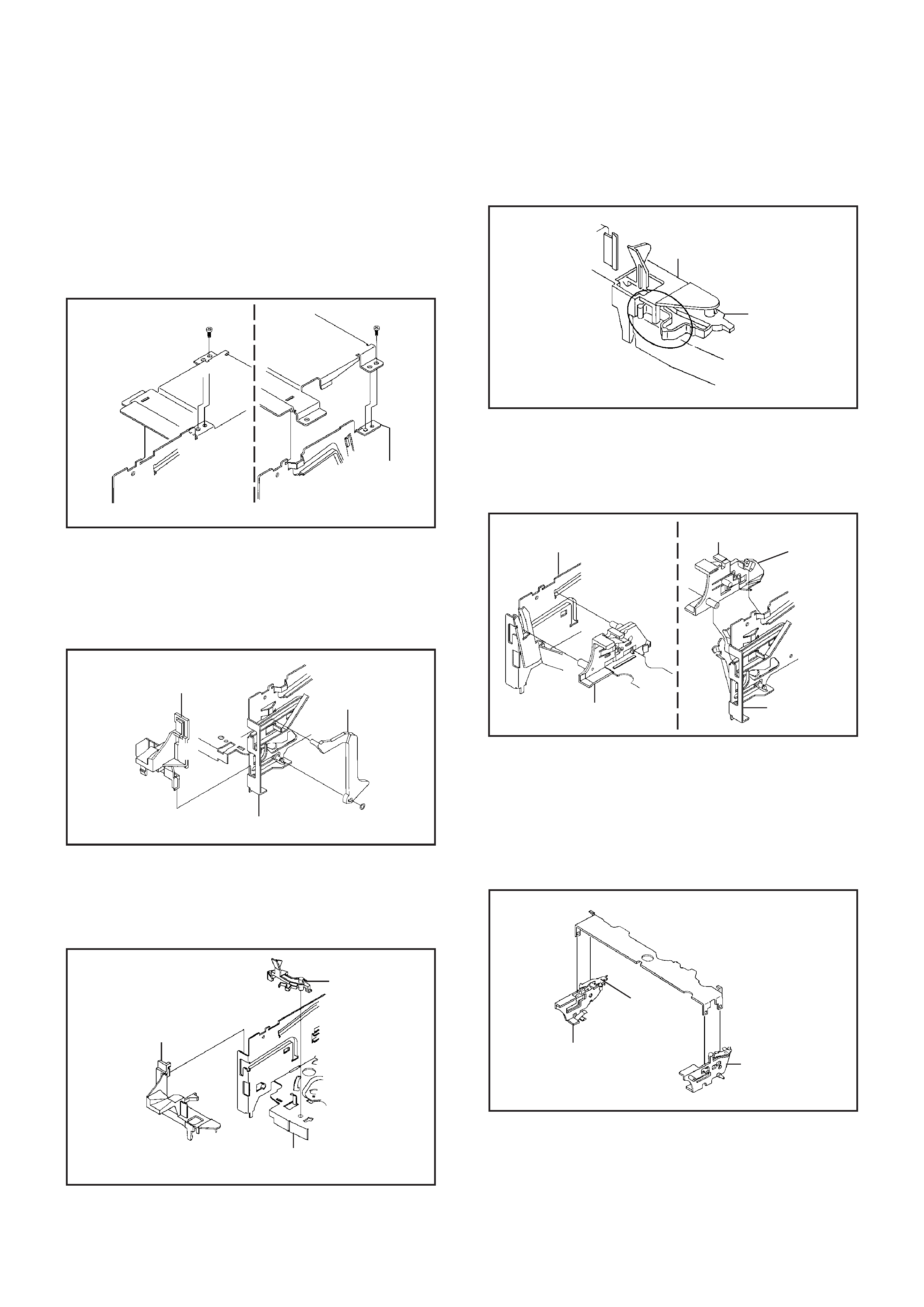
2. REMOVAL OF DECK PARTS
2-1: TOP BRACKET (Refer to Fig. 2-1)
Remove the 2 screws 1.
Slide the 2 supports 2 and remove the Top Bracket.
1.
2.
NOTE
When you install the Top Bracket, install the screw (1)
first, then install the screw (2).
1
(2)
Top Bracket
Top Bracket
Main Chassis
Main Chassis
2
1
(1)
2
Fig. 2-1
NOTE
When you install the Tape Guide L, install as shown in the
circle of Fig. 2-3-B. (Refer to Fig. 2-3-B)
REC Lever
Tape Guide L
· The REC Lever is not installed on the Video Cassette Player.
Fig. 2-3-B
2-4: CASSETTE HOLDER ASS'Y (Refer to Fig. 2-4)
Move the Cassette Holder Ass'y to the front side.
Push the Locker R to remove the Cassette Side R.
Remove the Cassette Side L.
1.
2.
3.
Main Chassis
Main Chassis
Cassette Side L
Cassette Side R
Locker R
Fig. 2-4
2-5: CASSETTE SIDE L/R (Refer to Fig. 2-5)
Unlock the 4 supports 1 and then remove the Cassette
Side L/R.
1.
· Screw Torque: 5
± 0.5kgf·cm
B2-1
2-2: FLAP LEVER/TAPE GUIDE R (Refer to Fig. 2-2)
NOTE
When you install the Cassette Side R, be sure to move the
Locker R after installing.
Cassette Side L
Cassette Side R
1
1
1
Locker R
1
Fig. 2-5
Move the Cassette Holder Ass'y to the back side.
Remove the Polyslider Washer 1.
Remove the Flap Lever.
Unlock the 3 supports 2 and remove the Tape Guide R.
1.
2.
3.
4.
Fig. 2-2
2-3: TAPE GUIDE L (Refer to Fig. 2-3-A)
Move the Cassette Holder Ass'y to the back side.
Unlock the 2 supports 1 and remove the Tape Guide L.
Remove the REC Lever. (Recorder only)
1.
2.
3.
1
Main Chassis
Tape Guide L
REC Lever
Fig. 2-3-A
· The REC Lever is not installed on the Video Cassette Player.
1
1
2
2
2
Tape Guide R
Flap Lever
Main Chassis