SERVICE MANUAL
DA
TA
BASIC VIDEO MECHANISM
: D33K-4HF/NT(6721R-0240A)<7100>
: D33K-4HD/NT(6721R-0220A)<610>
STEREO VIDEO
CASSETTE RECORDER
HV-FX7100
HV-FX610
S/M Code No. 09-006-346-9R1
BH
BH
REVISION
This Service Manual is the "Revision Publishing" and replaces "Simple Manual"
(S/M Code No. 09-006-346-9T1).
If requiring information about the VOLTAGE CHART of IC801, see the Supplement
Service manual of HV-FX7100 BH/FX610 BH (SM Code No. 09-006-346-9S1).

2
TABLE OF CONTENTS
SPECIFICATIONS ............................................................ 3
ACCESSORIES LIST ....................................................... 3
DISASSEMBLY INSTRUCTIONS ..................................... 4
SERVICE POSITION ........................................................ 5
VCR TEST TAPE INTERCHANGEABILITY TABLE ........ 6
ELECTRICAL MAIN PARTS LIST .............................. 7 ~ 8
TRANSISTOR ILLUSTRATION ........................................ 9
WIRE HARNESS DIAGRAM .......................................... 10
BLOCK DIAGRAM ................................................. 11 ~ 20
SCHEMATIC DIAGRAM
1. POWER SECTION ............................................. 21 ~ 22
2. TUNER/IF SECTION <7100> ............................ 23 ~ 24
3. TUNER/IF SECTION <610> ...................................... 25
4. AUDIO/VIDEO SECTION ................................... 27 ~ 28
5. SYSTEM CONTROL/SERVO/OSD SECTION .. 31 ~ 32
6. Hi-Fi AUDIO SECTION <7100> ......................... 33 ~ 34
7. JACK SECTION ......................................................... 41
8. KEY SECTION ........................................................... 41
VOLTAGE CHART
1. TUNER/IF SECTION .................................................. 26
2. AUDIO/VIDEO SECTION ........................................... 26
3. SYSTEM CONTROL/SERVO/OSD SECTION .......... 35
WAVEFORM
1. AUDIO/VIDEO SECTION ........................................... 29
2. SYSTEM CONTROL/SERVO/OSD SECTION .......... 30
FL DISPLAY ................................................................... 36
CIRCUIT BOARD DIAGRAM
1. MAIN C.B SECTION <7100> ............................. 37 ~ 38
2. MAIN C.B SECTION <610> ............................... 39 ~ 40
3. JACK C.B SECTION .................................................. 42
4. KEY C.B SECTION .................................................... 42
IC DESCRIPTION ................................................... 43 ~ 48
IC BLOCK DIAGRAM ..................................................... 49
ADJUSTMENT ........................................................ 50 ~ 51
MECHANICAL EXPLODED VIEW 1/1 ........................... 52
MECHANICAL MAIN PARTS LIST 1/1 ......................... 53
MECHANISM EXPLODED VIEW 1/3,2/3,3/3 ....... 54,56,58
MECHANISM MAIN PARTS LIST 1/3,2/3,3/3 ...... 55,57,59
DECK MECHANISM PARTS LOCATIONS
Top View .......................................................................... 60
Bottom View .................................................................... 60
DECK MECHANISM DISASSEMBLY
1. Drum Assembly ......................................................... 61
2. Plate Assembly Top ................................................... 63
3. Holder Assembly CST ............................................... 63
4. Guide CST ................................................................ 63
5. Bracket Side (L)/Bracket Assembly Door .................. 63
6. Arm Assembly F/L ..................................................... 63
7. Lever Assembly S/W ................................................. 63
8. Arm Assembly Cleaner .............................................. 64
9. Head F/E ................................................................... 64
10. Base Assembly A/C Head ........................................ 64
11. Brake Assembly S .................................................... 65
12. Brake Assembly T .................................................... 65
13. Arm Assembly Tension ............................................. 65
14. Reel S & Reel T ....................................................... 65
15. Support CST ............................................................ 66
16. Base Assembly P4 ................................................... 66
17. Opener Lid ............................................................... 66
18. Arm Assembly T/up .................................................. 66
19. Arm Assembly Pinch ................................................ 66
20. Belt Capstan/Motor Capstan .................................... 67
21.Clutch Assembly D33-K ............................................ 67
22. Lever F/R ................................................................. 67
23. Gear Assembly H-Up/D-K or
Gear Assembly Up/D-K ............................................ 67
24. Bracket Assembly Jog .............................................. 68
25. Guide Rack F/L, Gear Rack F/L ............................... 68
26. Brake Assembly Capstan ......................................... 68
27. Gear Drive/Gear Cam/Gear Connector ................... 69
28. Bracket Assembly L/D motor .................................... 69
29. Gear Sector .............................................................. 70
30. Base Tension/Plate Slider/Lever Tension ................. 70
31. Gear Assembly P3/Gear Assembly P2 .................... 71
32. Base Assembly P3/Base Assembly P2 .................... 71
33. Arm Assembly Idler or
Arm Assembly Idler Jog ............................................ 71
DECK MECHANISM ADJUSTMENT
Tools and Fixtures for service ......................................... 72
1. Mechanism Alignment Position Check ....................... 73
2. Preparation for Adjustment ........................................ 74
3. Checking Torque ........................................................ 74
4. Guide Roller Height Adjustment ................................. 75
4-1. Preliminary Adjustment .......................................... 75
4-2. Precise Adjustment ................................................ 75
5. Audio/Control (A/C) Head Adjustment ........................ 76
5-1. Preliminary Adjustment .......................................... 76
5-2. Confirm that the Tape Path smoothly between
the Take-up Guide and Pinch Roller ..................... 77
5-3. Precise Adjustment (Azimuth Adjustment) ............. 77
6. X-Value Adjustment .................................................... 77
7. Adjustment after Replacing Drum Assembly
(Video Heads) ............................................................. 78
8. Check the Tape Travel after Reassembling
Deck Assembly......................................................... 78
8-1. Checking Audio and RF Locking Time
during Playback and after CUE or REV ................ 78
8-2. Check for Tape Curling or Jamming ....................... 78
MAINTENANCE/INSPECTION PROCEDURE
1. Check before starting Repairs ................................... 79
2. Required Maintenance ............................................... 80
3. Scheduled Maintenance ............................................ 80
4. Supplies Required for Inspection and Maintenance .. 80
5. Maintenance Procedure ............................................. 80
5-1. Cleaning ................................................................. 80
5-2. Greasing ................................................................ 81
MECHANISM TROUBLESHOOTING GUIDE
1. Deck Mechanism ....................................................... 82
2. Front Loading Mechanism ......................................... 85

3
SPECIFICATIONS
Video recording system
Rotary 2 head helical scanning system
Video head
Double azimuth 4 head
Tuner system
Frequency synthesized tuner
TV system
M
Video signal system
NTSC color signal, 525 lines, 60 fields
M-PAL color signal, 525 lines, 60 fields
Usable cassettes
VHS video cassette
Recording/Playback time
SP: 3.5 hours with T-210 tape
LP: 7 hours with T-210 tape (playback only)
EP: 10.5 hours with T-210 tape
Tape speed
SP: 33.35 mm/sec
LP: 16.67 mm/sec
EP: 11.12 mm/sec
Fast-forward/Rewind time
less than 180 seconds with T-120 tape
Channel coverage
VHF: 2 to 13
UHF: 14 to 69
CATV: 5A, A-5 to A-1, A to W, W + 1 to W + 84
RF output
VHF channnel 3 or 4 (switchable), 66 dB
µ
Video input
1.0 Vp-p, 75 ohm, unbalanced
Video output
1.0 Vp-p, 75 ohm, unbalanced
Horizontal resolution
230 lines (SP mode)
Video S/N
43 dB (SP mode)
Audio track
<HV-FX7100>
3 tracks (Hi-Fi sound 2 tracks, Normal sound 1 track)
<HV-FX610>
Normal sound 1 track
Audio input
-6 dBm, 47 k ohm
Audio output
-6 dBm, less than 4.7 k ohm
Audio frequency response
normal: 100 Hz - 10 kHz (SP mode)
Hi-Fi: 20 Hz - 20 kHz (SP mode) <HV-FX7100>
Audio S/N
normal: more than 43 dB (SP mode)
Hi-Fi: more than 73 dB (SP mode) <HV-FX7100>
Hi-Fi dynamic range
more than 87 dB (SP mode) <HV-FX7100>
Operating temperature
5°C to 35°C
Power requirements
100 V - 240 V AC, 50/60 Hz
Power consumption
22 W <HV-FX7100>
19 W <HV-FX610>
TYP 3 W (stand by mode)
Dimensions
360 (W) x 94.5 (H) x 270 (D) mm
(141/
4 x 3
3/
4 x 10
3/
4 in.)
Weight
3.5 kg (7.7 lbs.)
· Design and specifications are subject to change without notice.
REF. NO
PART NO.
KANRI
DESCRIPTION
NO.
ACCESSORIES LIST
1
8A-JFR-901-010
IB,BH(P)-FX610<610.>
1
8A-JFP-901-010
IB,BH(P)-FX7100<7100>
2
S7-11R-1N0-43A
REMOTE CONTROLLER ASSY
3
8A-JPF-607-010
CABLE,ASSY
4
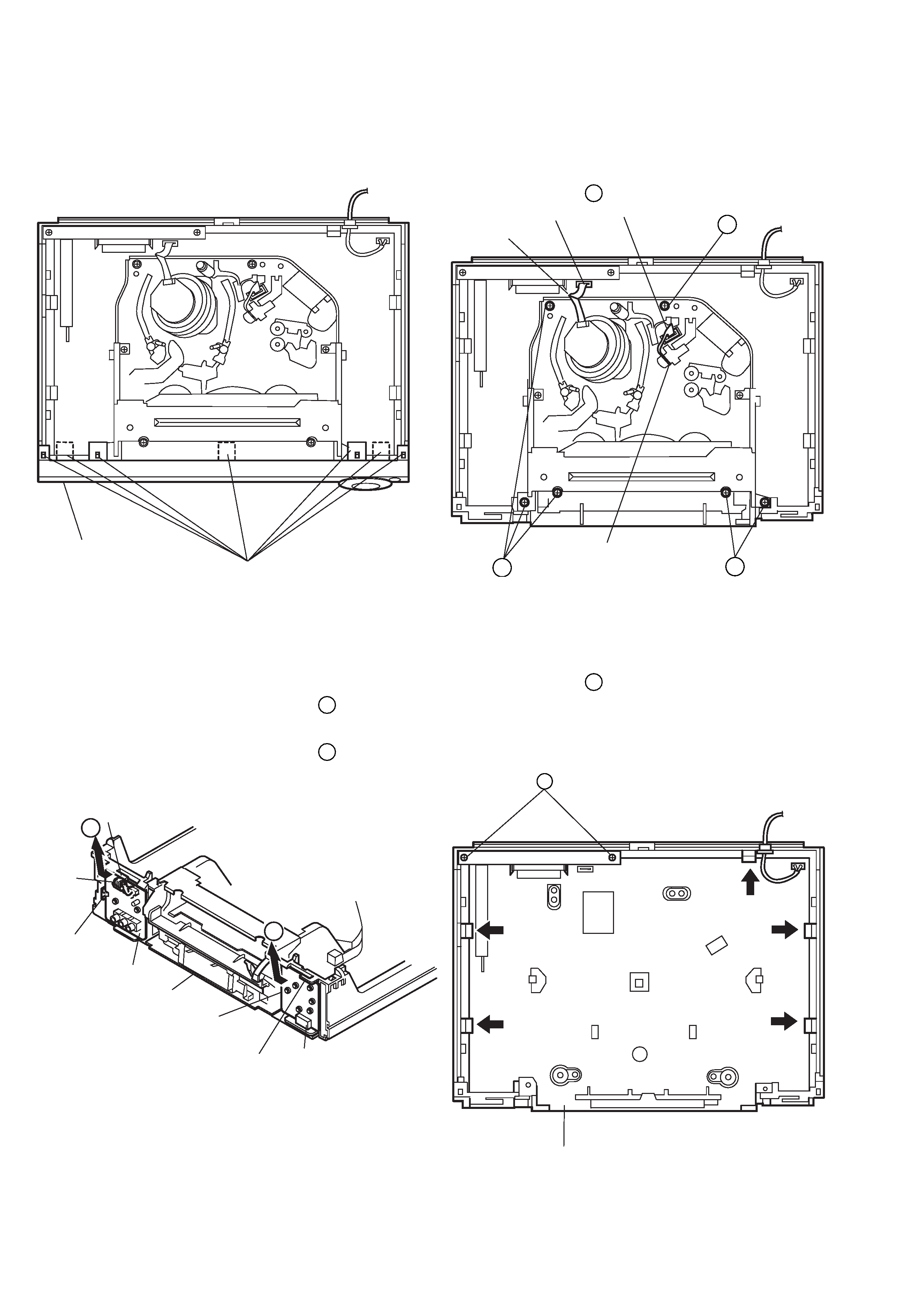
DISASSEMBLY INSTRUCTIONS
1. Top Case Removal
1) Remove 4 screws holding the top case.
2. Panel Front Removal (see Fig. 1)
1) Release 7 tabs, and then remove the panel front.
Fig. 1
3. Jack C.B. and Key C.B. Removal (see Fig. 2)
1) Release 2 tabs, and then remove Jack C.B. from the con-
nector (P9M02) in the direction of arrow 1 .
2) Release the tab, and then remove Key C.B. from the con-
nector (P9M01) in the direction of arrow 2 .
Fig. 2
4. Mechanism Removal (see Fig. 3)
1) Disconnect the drum FF cable from the connector
(PMD01) on the Main C.B.
2) Disconnect the ACE head FF cable from the connector
(P3D02) on the Main C.B.
3) Remove 6 screws A .
Fig. 3
5. Main C.B. Removal (see Fig. 4)
1) Remove 2 screws B holding the panel assy, distri-butor.
2) Release 5 tabs, and then simultaneously lift the panel as-
sembly, distributor and Main C.B. to remove them.
Fig. 4
PANEL
FRONT
TAB
TAB
TAB
TAB
KEY C.B
JACK C.B
MAIN C.B
P9M02
P9M01
1
2
FF CABLE
P3D02
FF CABLE
PMD01
A
A
A
PANEL ASSY,
DISTRIBUTOR
MAIN C.B
TAB
TAB
TAB
TAB
TAB
B
5
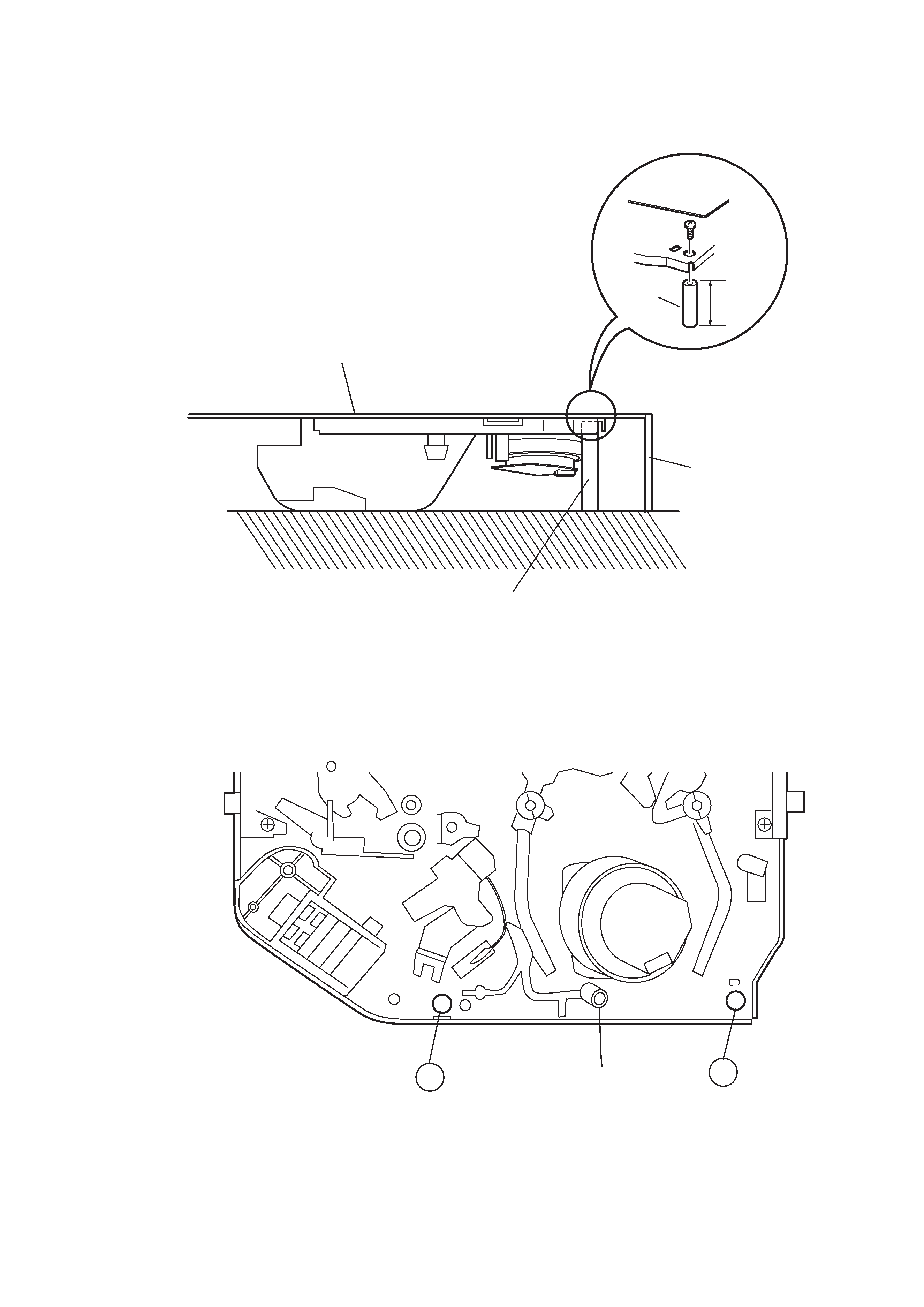
SERVICE POSITION
To set the mechanism to the service position in active status:
Insert a spacer as shown below: The service position can be set in the stable status without any defective contact.
Location
Install spacers at locations (A) and (B).
MAIN C.B
D33 MECHANISM
SPARSER
60mm
MAIN C.B
D33
MECHA
SPARSER
REAR PANEL
A
B
Top View
CYLINDER
HEAD CLEANER