SERVICE MANUAL
DA
TA
K(S),EZ(S,L)
K(S),EZ(S)
S/M Code No. 09-027-457-9R2
REVISION
· This Service Manual is the "Revision Publishing" and replaces "Simple Manual"
(S/M Code No.09-027-457-9T2)
CD STEREO RADIO
CASSETTE RECORDER
BASIC TAPE MECHANISM:AZM-6 YR3NC
BASIC CD MECHANISM :KSM-213 RDM
CSD-TD29
CSD-TD69

-2-
· Design and specifications are subject to change without notice.
SPECIFICATIONS -1/1
Tuner section
Frequency range, antenna FM: 87.5 - 108.0 MHz Rod antenna, MW:
531/530 - 1,602/1,710 kHz (9/10 kHz step) Ferrite bar antenna, LW: 144 -
290 kHz Ferrite bar antenna
Deck section
Track format 4 tracks, 2 channels / Frequency range Normal tape: 50 -
12,500 Hz (EIAJ) / Recording system AC bias / Erasing system AC
erase / Heads Recording/playback head (1), Erasure head (1)
CD player section
Disc Compact disc / Scanning method Non-contact optical scanner
(semiconductor laser)
General<EZ>
Speaker 100 mm cone type (2) / Output Headphones jack (stereo mini-
jack) / Power output 2.9 W + 2.9 W (DIN USIC POWER), 2.5 W + 2.5 W
(EIAJ 7 ohms, T.H.D. 10% DC), 1.8 W + 1.8 W (DIN 1% Rated Power) /
Power requirements C 12 V using eight size C (R14) batteries, AC 230
V, 50 Hz / Power consumption 16 W / Dimensions (W × H × D) 414 ×
181 × 240.4 mm / Weight (excluding batteries) 3.2 kg
General<K>
Speaker 100 mm cone type (2) / Output Headphones jack (stereo mini-
jack) / Power output 2.5 W + 2.5 W (EIAJ 7 ohms, T.H.D. 10% DC), 1.8
W + 1.8 W (DIN 1% Rated Power) / Power requirements C 12 V using
eight size C (R14) batteries, AC 230 V, 50 Hz / Power consumption 16
W / Dimensions (W × H × D) 414 ×
181 × 240.4 mm / Weight (excluding batteries) 3.2 kg
-3-
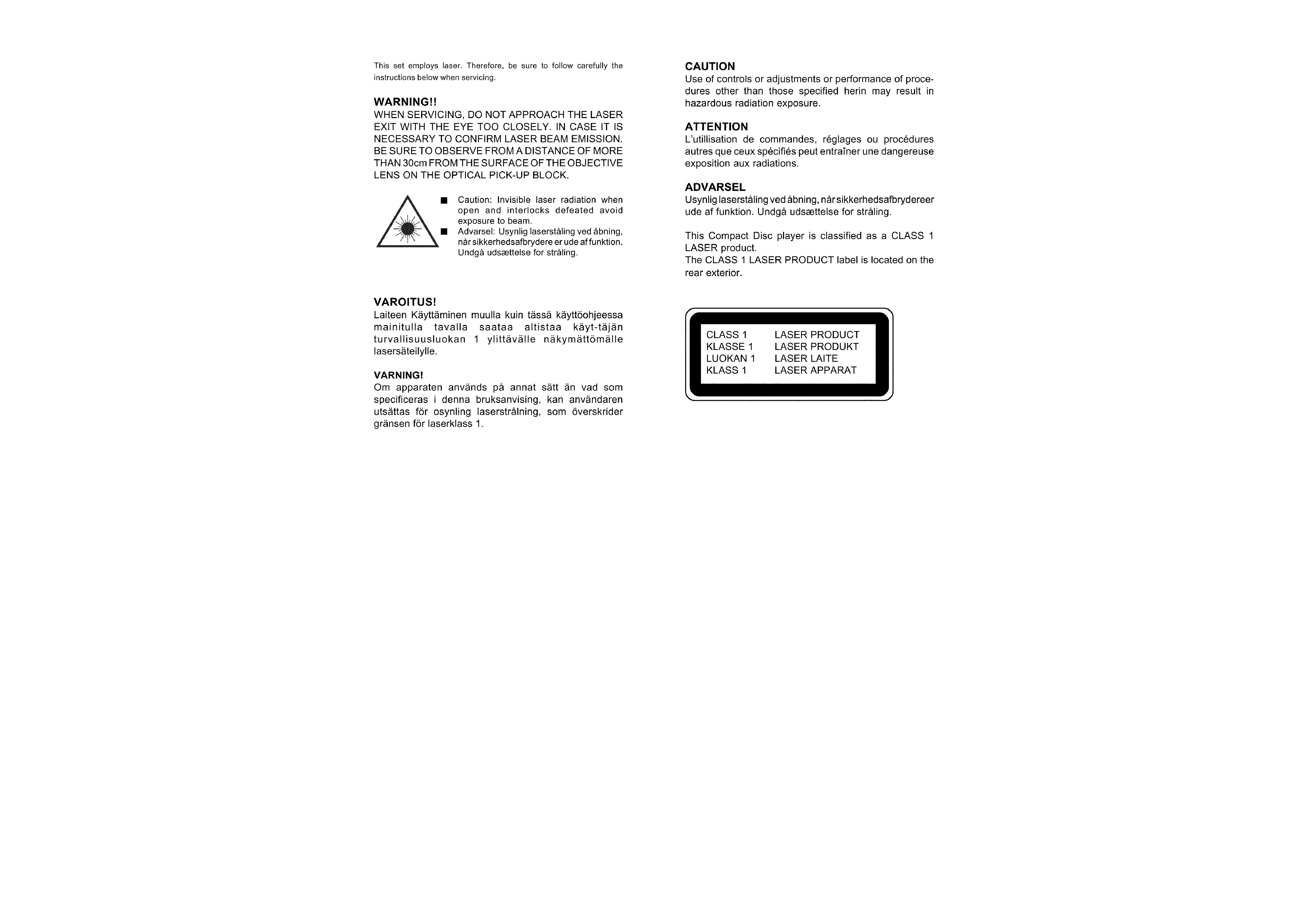
PROTECTION OF EYES FROM LASER BEAM DURING SERVICING -1/1
-4-
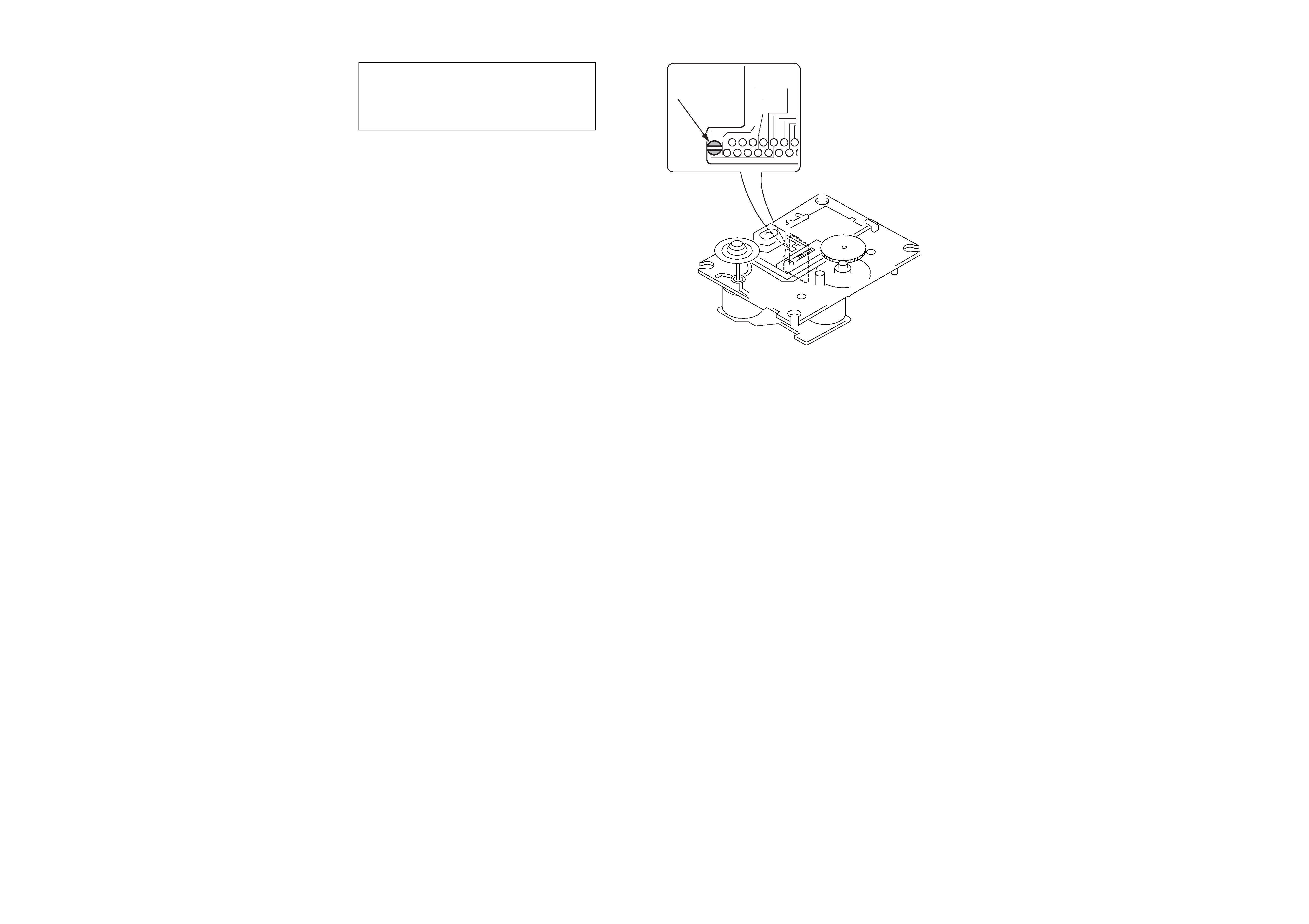
PRECAUTION TO REPALCE OPTICAL BLOCK (KSM-213 RDM) -1/1
1) After the connection, remove solder shown in
the right figure.
Body or clothes electrostatic potential could ruin
laser diode in the optical block. Be sure ground
body and workbench, and use care the clothes
do not touch the diode.
Solder

!
= ! SAFTY PARTS
C
= Components marked
All components used on this model at the production line are shown in this service manual.
However, please note that not all components will be available as spare parts for after-sales service.
Components marked S and O are designated as spare parts for service and will be stocked at the spare parts centers.
Components marked X and R are not designated as spare parts for after sales service, and will not be stocked at the spare parts centers.
UNIT-NAME
! C REF-NO PARTS-NO
PARTS-NAME
SUFFIX&MODEL
-5-
ACCESSORIES PARTS LIST -1/1
CSD-TD29
CSD-TD29
CSD-TD29
CSD-TD69
CSD-TD69
KSC
EZSC
EZLC
KSC
EZSC
! O AS1001
87-099-726-010 PLUG,ADPTR CONV(K)
a
.
.
d
.
! O AS1002
87-A80-081-010 AC CORD SET ASSY,EZ BLK
a
b
c
d
e
O AS1003
8C-CHE-951-010 RC UNIT,RC-CAT1
.
.
.
d
e
O AS1004
8C-CHA-905-010 IB,K(E)FM TD29/69
a
.
.
d
.
O AS1005
8C-CHA-906-010 IB,EZ(9L)FM TD29/69
.
b
c
.
e
! O AS1006
87-099-726-010 PLUG,ADPTR CONV(K)
a
.
.
d
.