SERVICE MANUAL
DA
TA
STEREO CAR CD RECEIVER
BASIC CD MECHANISM : CDC02AW1
CDC-R307
CDC-RV407
YZ
YZ
S/M Code No. 09-004-429-0R1
REVISION
· This Service Manual is the "Revision Publishing" and replaces "Simple Manual"
(S/M Code No. 09-002-429-0T1).

2
RADIO SECTION
(FM)
Frequency Range
87.5 MHz 108 MHz (50 kHz steps)
Usable Sensitivity
12.7 dBf
50 dB Quieting Sensitivity
17.2 dBf
IF Rejection
80 dB
Frequency Response
30 Hz 15,000 Hz
S/N Ratio
63 dB
Stereo Separation
35 dB at 1 kHz
Alternate Channel Selectivity 70 dB
Capture Ratio
3 dB
(MW)
Frequency Range
531 kHz 1,602 kHz (9 kHz steps)
Usable Sensitivity
30
µV (30 dB)
(LW)
Frequency Range
144 kHz 288 kHz
(1 -kHz/9 -kHz steps)
Usable Sensitivity
30
µV (30 dB)
CD SECTION
Frequency Response
17 Hz 20 kHz +0/3 dB
Dynamic Range
More than 80 dB
Channel Separation
More than 65 dB
S/N Ratio
More than 85 dB
Wow/Flutter
Unmeasurable
AUDIO SECTION
Max. Power Output
45 W x 4 channels
AUX IN input
Input Sensitivity (load impedance)
AUX IN
300 mV (10 k
)
GENERAL
Power Supply Voltage
14.4 V (11 to 16 V allowable),
DC, negative ground
Load Impedance
4
Tone Control
Bass
±10 dB at 100 Hz
Treble
±10 dB at 10 kHz
Preamp Output Voltage (load impedance)
2.2 V (10 k
)
Installation Size
182 (W) x 53 (H) x 155 (D) mm
(71/
4 (W) x 2
1/
8 (H) x 6
1/
8 (D) inches)
STEERING-WHEEL-MOUNTED REMOTE CONTROL UNIT
Dimensions
Approx. 67 (W) x 26 (H) x 27 (D) mm
(23/
4 (W) x 1
1/
16 (H) x 1
1/
8 (D) inches)
(excluding holder)
Weight
Approx. 38 g (1.33 oz.)
(including holder, battery)
SPECIFICATIONS
· Design and specifications are subject to change without notice.
ACCESSORIES / PACKAGE LIST
DESCRIPTION
REF. NO.
KANRI
NO.
PART NO.
1
8A-KCG-905-010
IB,INST YZ(9L)-I
1
8A-KC4-901-010
IB,YZ(9L) R307,RV407
2
8Z-KC1-030-010
CASE,DFP-C
3
8Z-KC1-231-110
HLDR,HALF-C
4
8Z-KC1-235-010
HLDR,REAR MTG
5
8Z-KC1-232-010
KEY,REMOVE-C
6
87-B10-141-010
NUT,5 TYPE-2
7
87-B10-144-010
W,5.2-10-0.5
8
87-B10-145-010
W-SPR,5.3-8.5-1.5
9
87-B10-143-010
UT1+5-15 W/O SLOT
10
87-B10-216-010
U+2.6-4.0 ZINC BLK(BH M2.6)
11
8Z-KC1-244-010
S-SCREW,5*6 TH+TAPPING ST
12
8Z-KC1-250-010
S-SCREW,HEXAGON
*13
R8-AZR-190-040
AZR-1 RCKCGNF
* NOTE: This remote controller is not an accessory part.
It is an individual model.
3
This set employs laser. Therefore, be sure to follow carefully the
instructions below when servicing.
WARNING!!
WHEN SERVICING, DO NOT APPROACH THE LASER
EXIT WITH THE EYE TOO CLOSELY. IN CASE IT IS
NECESSARY TO CONFIRM LASER BEAM EMISSION.
BE SURE TO OBSERVE FROM A DISTANCE OF MORE
THAN 30cm FROM THE SURFACE OF THE OBJECTIVE
LENS ON THE OPTICAL PICK-UP BLOCK.
Caution: Invisible laser radiation when
open and interlocks defeated avoid
exposure to beam.
Advarsel: Usynlig laserståling ved åbning,
når sikkerhedsafbrydere er ude af funktion.
Undgå udsættelse for stråling.
VAROITUS!
Laiteen Käyttäminen muulla kuin tässä käyttöohjeessa
mainitulla
tavalla
saataa
altistaa
käyt-täjän
turvallisuusluokan 1 ylittävälle näkymättömälle
lasersäteilylle.
VARNING!
Om apparaten används på annat sätt än vad som
specificeras i denna bruksanvising, kan användaren
utsättas för osynling laserstrålning, som överskrider
gränsen för laserklass 1.
PROTECTION OF EYES FROM LASER BEAM DURING SERVICING
CAUTION
Use of controls or adjustments or performance of proce-
dures other than those specified herin may result in
hazardous radiation exposure.
ATTENTION
L'utillisation de commandes, réglages ou procédures
autres que ceux spécifiés peut entraîner une dangereuse
exposition aux radiations.
ADVARSEL
Usynlig laserståling ved åbning, når sikkerhedsafbrydereer
ude af funktion. Undgå udsættelse for stråling.
This Compact Disc player is classified as a CLASS 1
LASER product.
The CLASS 1 LASER PRODUCT label is located on the
rear exterior.
CLASS 1
LASER PRODUCT
KLASSE 1
LASER PRODUKT
LUOKAN 1
LASER LAITE
KLASS 1
LASER APPARAT
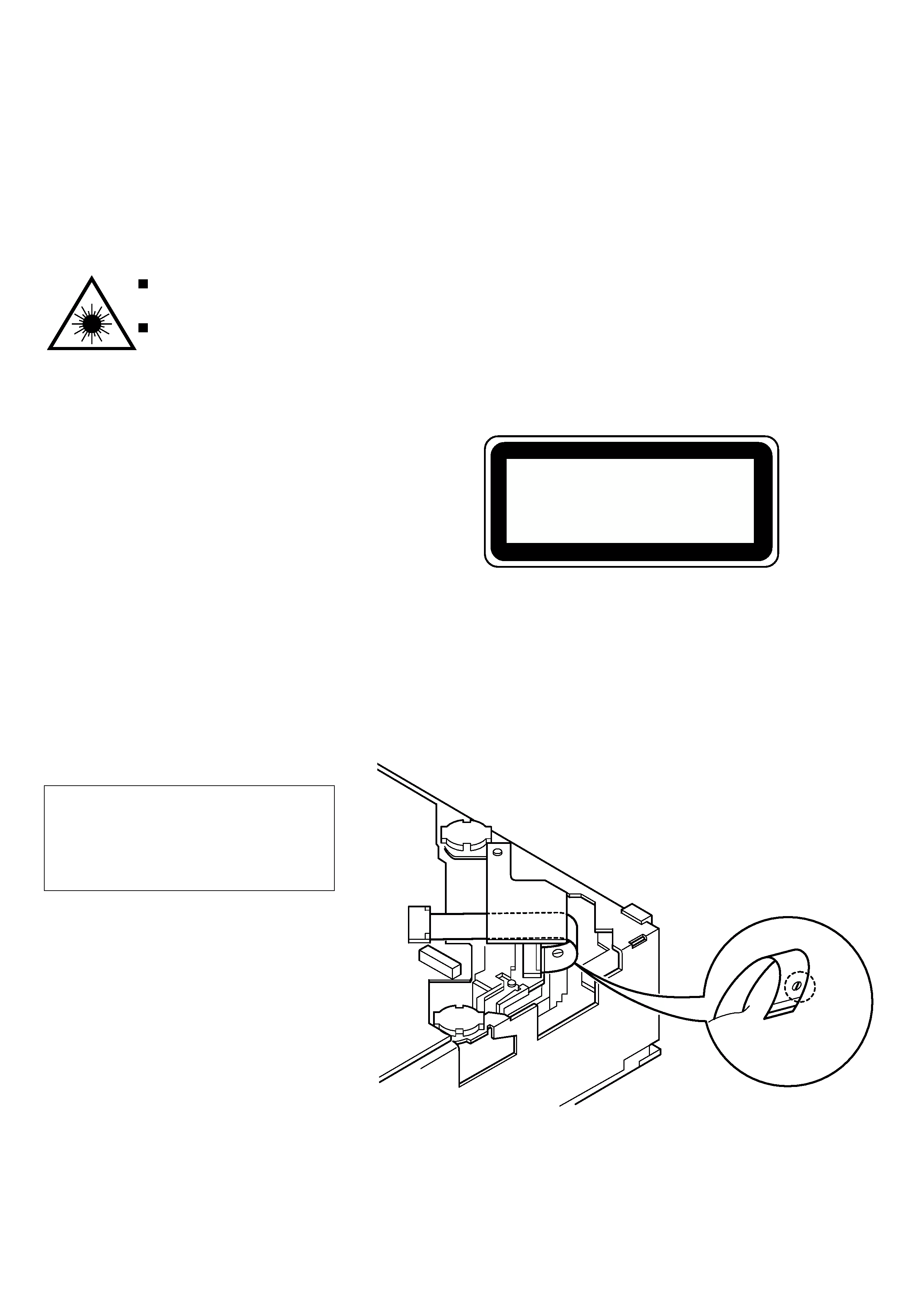
Precaution to replace Optical block
(KSS 710A)
Body or clothes electrostatic potential could
ruin laser diode in the optical block. Be sure
ground body and workbench, and use care
the clothes do not touch the diode.
1) After the connection, remove solder
shown in right figure.
Solder
CAUTION WHEN SERVICING
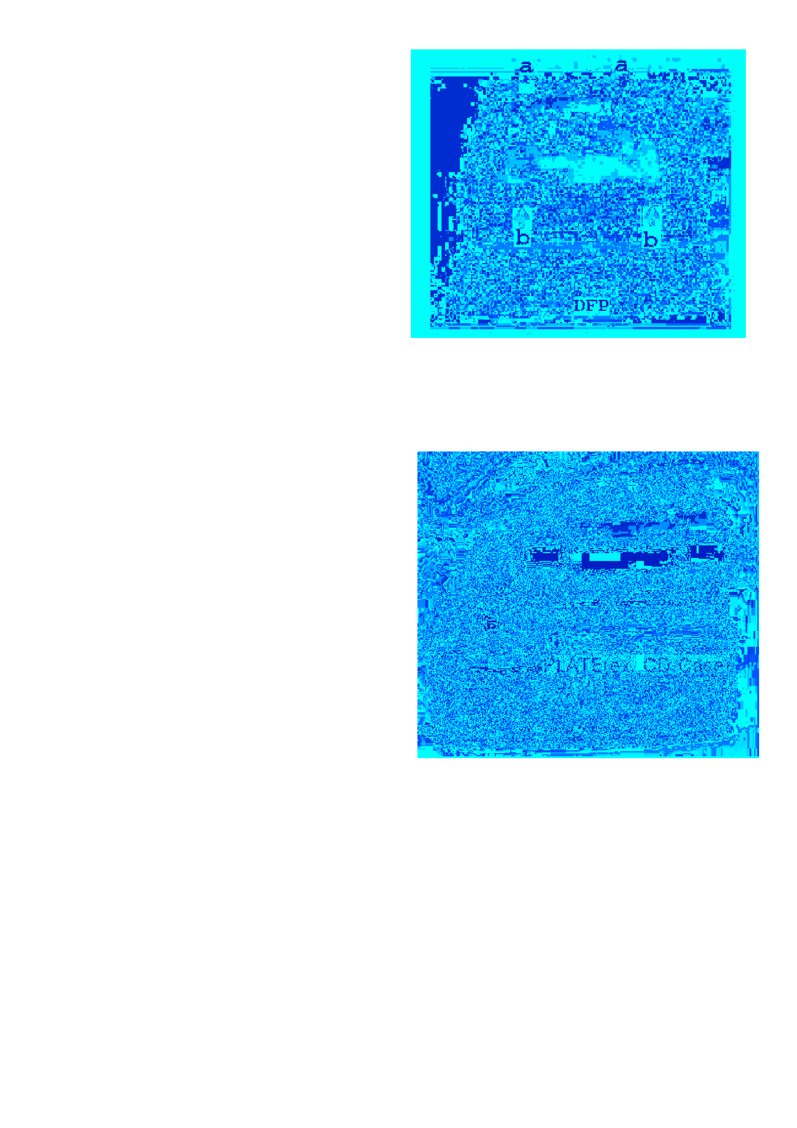
2. Servicing Position
Put the DFP onto the CD case to fix it. (Fig. 2)
1. Disassembly Instruction
1) Remove the COVER TOP and COVER BOTTOM.
2) Remove the DFP.
3) Remove the four screws (indicated by arrows) from CD
mechanism. (Fig. 1)
Screw (a)
× 2: VTT 2.6-6
Screw (b)
× 2: VTT 2.6-3B
Fig. 1
Fig. 2
4

5
ELECTRICAL MAIN PARTS LIST
DESCRIPTION
REF. NO.
KANRI
NO.
PART NO.
DESCRIPTION
REF. NO.
KANRI
NO.
PART NO.
IC
88-KT1-606-080
IC,PST994D
8Z-KT1-622-010
C-IC,LC75374E
87-A21-562-010
IC,LA4743B
87-A21-528-030
C-IC,UPD178018AGC-554-3B9
87-020-784-080
IC,TC4053BF
88-KT1-608-010
C-IC,LC75854W
87-A90-951-010
RCR UNIT,SBX1971-52
87-A21-467-010
C-IC,CXA2581N
87-A21-533-030
C-IC,CXD2587Q
87-017-888-080
IC,NJM4558MD
87-A21-534-030
C-IC,UPD78012FGC-656-AB8
87-A21-161-040
C-IC,BA6392FP
87-A20-712-040
C-IC,BA6417F
88-KT1-607-080
C-IC,SAA6579T
TRANSISTOR
87-A30-287-040
C-TR,DTC114TKA
87-A30-289-040
C-TR,2SA1037AK(R)
89-324-122-080
C-TR,2SC2412KR
87-A30-290-010
TR,KTA1658(Y)
87-A30-291-010
TR,KTC4369(Y)
89-418-580-080
TR,2SD1858-TV2
89-423-953-010
TR,2SD2395F
89-113-625-080
C-TR,2SA1362GR
87-A30-283-040
C-TR,DTA114YKA
87-A30-248-040
C-TR,2SB1197KQ
87-A30-011-080
C-TR,DTB113ZK
87-A30-273-040
C-TR,DTC124EKA
87-026-210-040
C-TR,DTC144EK
DIODE
87-A40-250-080
C-DIODE,DAN217
87-A40-649-080
ZENER,MTZJ11A
87-A40-509-080
ZENER,MTZJ6.8C
87-020-330-080
DIODE,DAP202K
87-A40-620-080
ZENER,MTZJ6.2A
87-A40-650-080
ZENER,MTZJ6.8A
87-017-932-080
ZENER,MTZJ6.2B
87-070-136-080
ZENER,MTZJ5.1B
87-A40-798-010
DIODE,1N5402(3A/200V)
87-020-465-080
DIODE,1SS133
87-020-331-080
C-DIODE,DAN202K
87-A40-523-080
ZENER,MTZJ9.1B
87-A40-337-080
ZENER,MTZJ6.8B
87-001-783-080
DIODE,1N4002
87-020-331-080
C-DIODE,DAN202K
MAIN C.B
ANT101
8Z-KT1-614-010
ANT,AW-002
C101
87-010-178-080
CHIP CAP,1000P
C102
87-010-197-080
CAP,CHIP 0.01 DM
C103
87-010-186-080
C-CAP,S 4700P-50 KB
C104
87-010-186-080
C-CAP,S 4700P-50 KB
C105
87-010-490-040
CAP,E 0.1-50 M 5L
C106
87-010-198-080
CAP,CHIP 0.022
C107
87-010-198-080
CAP,CHIP 0.022
C108
87-018-131-080
CAP,TC U 1000P-50 KB
C109
87-010-197-080
CAP,CHIP 0.01 DM
C111
87-010-196-080
CHIP CAPACITOR,0.1-25
C112
87-010-197-080
CAP,CHIP 0.01 DM
C113
87-010-197-080
CAP,CHIP 0.01 DM
C115
87-010-178-080
CHIP CAP,1000P
C116
87-010-197-080
CAP,CHIP 0.01 DM
C117
87-010-197-080
CAP,CHIP 0.01 DM
C118
87-010-197-080
CAP,CHIP 0.01 DM
C119
87-010-495-040
CAP,E 2.2-50 GAS
C120
87-010-185-080
C-CAP,S 3900P-50 B
C121
87-010-220-080
C-CAP,S 0.018-25BK
C122
87-010-220-080
C-CAP,S 0.018-25BK
C123
87-012-358-080
C-CAP,S 0.47-10 FZ
C124
87-012-358-080
C-CAP,S 0.47-10 FZ
C131
87-010-182-080
C-CAP,S 2200P-50 KB
C132
87-010-182-080
C-CAP,S 2200P-50 KB
C151
87-012-149-080
C-CAP,S 30P-50 J CH
C152
87-010-315-080
C-CAP,S 27P-50 J CH
C153
87-010-495-040
CAP,E 2.2-50 M 5L
C154
87-012-157-080
C-CAP,S 330P-50 J CH
C155
87-010-175-080
CHIP CAP,560P-50 J SL
C156
87-010-196-080
CHIP CAPACITOR,0.1-25
C157
87-010-553-040
CAP,E 47-16 M 5L
C202
87-012-358-080
C-CAP,S 0.47-10 FZ
C203
87-010-196-080
CHIP CAPACITOR,0.1-25
C205
87-010-553-040
CAP,E 47-16 GAS
C206
87-010-198-080
CAP,CHIP 0.022
C207
87-010-196-080
CHIP CAPACITOR,0.1-25
C208
87-010-196-080
CHIP CAPACITOR,0.1-25
C209
87-010-196-080
CHIP CAPACITOR,0.1-25
C211
87-010-198-080
CAP,CHIP 0.022
C212
87-010-196-080
CHIP CAPACITOR,0.1-25
C214
87-010-196-080
CHIP CAPACITOR,0.1-25
C216
87-010-198-080
CAP,CHIP 0.022
C217
87-010-196-080
CHIP CAPACITOR,0.1-25
C218
87-010-196-080
CHIP CAPACITOR,0.1-25
C219
87-010-182-080
C-CAP,S 2200P-50 B
C220
87-010-553-040
CAP,E 47-16 GAS
C251
87-012-368-080
C-CAP,S 0.1-50 ZF
C252
87-010-182-080
C-CAP,S 2200P-50 B
C301
87-012-358-080
C-CAP,S 0.47-10 FZ
C302
87-012-358-080
C-CAP,S 0.47-10 FZ
C303
87-010-805-080
CAP,S 1-16
C304
87-010-805-080
CAP,S 1-16
C305
87-010-184-080
CHIP CAPACITOR,3300P(K)
C306
87-010-184-080
CHIP CAPACITOR,3300P(K)
C307
87-010-198-080
CAP,CHIP 0.022
C308
87-010-198-080
CAP,CHIP 0.022
C309
87-010-805-080
C-CAP,S 1-16 ZF
C310
87-010-805-080
C-CAP,S 1-16 ZF
C311
87-A11-177-080
C-CAP,S 0.15-16 KB
C312
87-A11-177-080
C-CAP,S 0.15-16 KB
C313
87-A11-177-080
C-CAP,S 0.15-16 KB
C314
87-A11-177-080
C-CAP,S 0.15-16 KB
C315
87-010-805-080
C-CAP,S 1-16 ZF
C316
87-010-805-080
C-CAP,S 1-16 ZF
C317
87-010-196-080
CHIP CAPACITOR,0.1-25
C318
87-010-498-040
CAP,E 10-16 GAS
C321
87-010-555-040
CAP,E 100-10 GAS
C322
87-010-198-080
CAP,CHIP 0.022
C331
87-A11-062-080
C-CAP,S 2.2-16 ZF
C332
87-A11-062-080
C-CAP,S 2.2-16 ZF
C333
87-A11-062-080
C-CAP,S 2.2-16 ZF
C334
87-A11-062-080
C-CAP,S 2.2-16 ZF
C335
87-010-491-040
CAP,E 0.22-50 GAS
C336
87-010-491-040
CAP,E 0.22-50 GAS
C339
87-010-805-080
CAP,S 1-16
C340
87-010-805-080
CAP,S 1-16
C342
87-012-140-080
CAP,470P
C344
87-012-140-080
CAP,470P
C401
87-010-494-040
CAP,E 1-50 M 5L SRE
C405
87-010-196-080
CHIP CAPACITOR,0.1-25
C406
87-010-196-080
CHIP CAPACITOR,0.1-25
C407
87-012-358-080
C-CAP,S 0.47-10 FZ
C408
87-012-358-080
C-CAP,S 0.47-10 FZ
C409
87-010-805-080
C-CAP,S 1-16 ZF
C410
87-010-805-080
C-CAP,S 1-16 ZF
C451
87-012-358-080
C-CAP,S 0.47-10 FZ
C452
87-012-358-080
C-CAP,S 0.47-10 FZ