BASIC CD MECHANISM :
CD MECHANISM
AZG-1
S/M Code No. 09-001-335-3N2
SERVICE MANUAL
KSM-880CAB
DA
TA
TYPE
Z8RMDJM
English
2
PROTECTION OF EYES FROM LASER BEAM DURING SERVICING
VAROITUS!
Laiteen Käyttäminen muulla kuin tässä käyttöohjeessa mainit-
ulla tavalla saattaa altistaa käyt-täjän turvallisuusluokan 1 ylit-
tävälle näkymättömälle lasersäteilylle.
VARNING!
Om apparaten används på annat sätt än vad som specificeras i
denna bruksanvising, kan användaren utsättas för osynling
laserstrålning, som överskrider gränsen för laserklass 1.
Caution: Invisible laser radiation when
open and interlocks defeated avoid expo-
sure to beam.
Advarsel:Usynling laserståling ved åbning,
når sikkerhedsafbrydere er ude af funktion.
Undgå udsættelse for stråling.
CAUTION
Use of controls or adjustments or performance of procedures
other than those specified herein may result in hazardous
radiation exposure.
ATTENTION
L'utilisation de commandes, réglages ou procédures autres que
ceux spécifiés peut entraîner une dangereuse exposition aux
radiations.
ADVARSEL!
Usynlig laserståling ved åbning, når sikkerhedsafbrydereer ude
af funktion. Undgå udsættelse for stråling.
This Compact Disc player is classified as a CLASS 1 LASER
product.
The CLASS 1 LASER PRODUCT label is located on the rear
exterior.
This set employs laser. Therefore, be sure to follow carefully the
instructions below when servicing.
WARNING!
WHEN SERVICING, DO NOT APPROACH THE LASER EXIT
WITH THE EYE TOO CLOSELY. IN CASE IT IS NECESSARY TO
CONFIRM LASER BEAM EMISSION. BE SURE TO OBSERVE
FROM A DISTANCE OF MORE THAN 30cm FROM THE
SURFACE OF THE OBJECTIVE LENS ON THE OPTICAL
PICK-UP BLOCK.
CLASS 1
KLASSE 1
LUOKAN 1
KLASS 1
LASER PRODUCT
LASER PRODUKT
LASER LAITE
LASER APPARAT
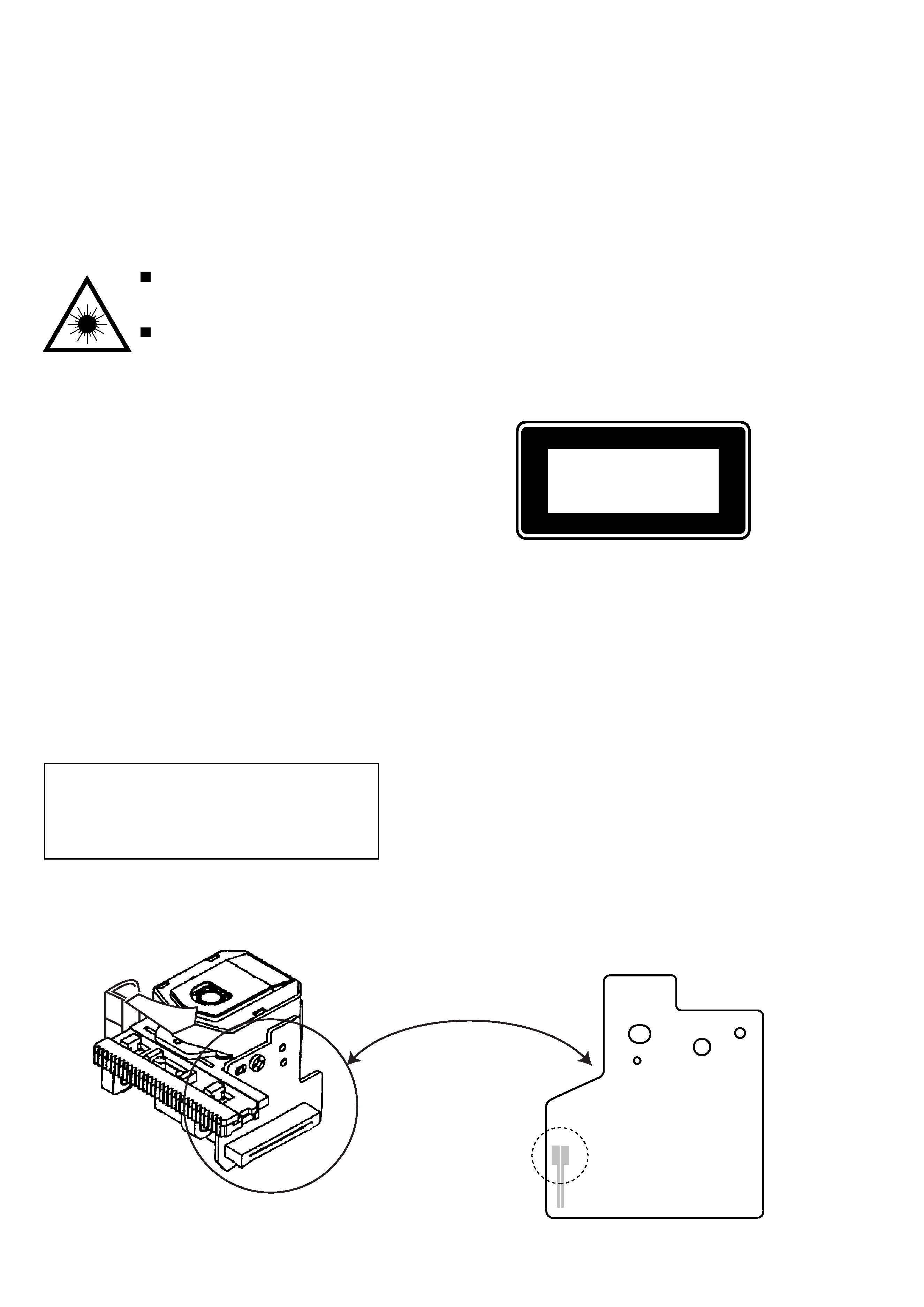
Precaution to replace Optical block
1) After the connection, remove solder shown in
the figure below.
Body or clothes electrostatic potential could ruin
laser diode in the optical block. Be sure ground
body and workbench, and use care the clothes
do not touch the diode.
Solder
3
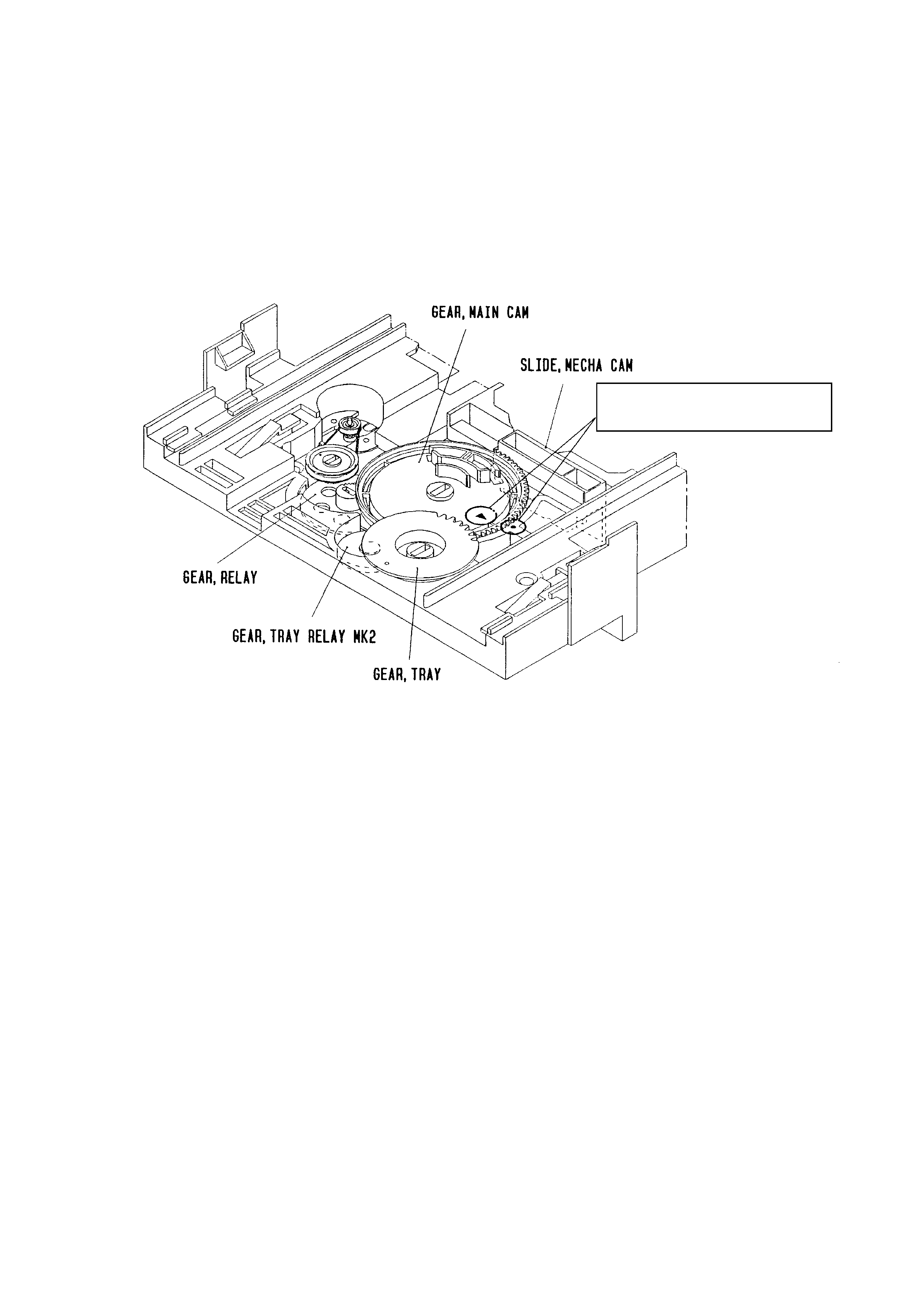
How to Adjust the Rotating Phase of the
Gear, Main Cam
1) Push down the hooking catch of the CHAS. MECH, and
remove the TRAY.
2) Align the arrow mark of the Gear, Main Cam with the black
round mark of the CHAS, MECHA as shown below.
3) Confirm that the Slide, Mech Cam is located in the right
position, then insert the TRAY gently.
Caution: If the rotating phase of the Gear, Main Cam is
incorrectly adjusted, the chucking operation and
tray movement will have malfunction.
Align the arrow
2 mark with the black
round · mark.

4
REF. NO
PART NO.
KANRI
DESCRIPTION
NO.
REF. NO
PART NO.
KANRI
DESCRIPTION
NO.
ELECTRICAL MAIN PARTS LIST
IC
87-A20-446-010
C-IC,LA9241ML
87-A21-319-010
C-IC,LC78622NE
87-A20-445-010
IC,BA5936
TRANSISTOR
87-026-609-080
TR,KTA1266GR
87-026-295-080
TR,DTC144TK
87-A30-087-080
C-FET,2SK2158
87-026-237-080
CHIP-TR,DTC124XK
87-A30-076-080
C-TR,2SC3052F
87-A30-075-080
C-TR,2SA1235F
DIODE
87-020-465-080
DIODE,1SS133 (110MA)
87-020-331-080
CHIP-DIODE,DAN202K
87-A40-337-080
ZENER,MTZJ 6.8B
87-A40-313-080
C-DIODE,MC 2840
87-A40-620-080
ZENER,MTZJ6.2A
3CD C.B
C11
87-012-393-080
C-CAP,S 0.22-16 R K
C12
87-012-157-080
C-CAP,S 330P-50 CH
C13
87-016-369-080
C-CAP,S 0.033-25 B K
C14
87-A10-201-080
C-CAP,S0.33-16 KB
C15
87-010-213-080
C-CAP,S 0.015-50 B
C16
87-016-083-080
C-CAP,S 0.15-16 RK
C17
87-010-184-080
CHIP CAPACITOR 3300P(K)
C18
87-A11-177-080
C-CAP,S 0.15-16 K B
C19
87-010-992-080
C-CAP,S 0.047-25 B
C20
87-010-178-080
CHIP CAP 1000P
C21
87-012-393-080
C-CAP,S 0.22-16 R K
C22
87-016-083-080
C-CAP,S 0.15-16 RK
C23
87-010-197-080
CAP, CHIP 0.01 DM
C24
87-010-186-080
CAP,CHIP 4700P
C25
87-010-400-040
CAP,E 0.47-50
C26
87-010-322-080
C-CAP,S 100P-50 CH
C27
87-010-382-040
CAP,E 22-25 SME
C28
87-010-545-040
CAP,E 0.22-50 SME
C29
87-010-184-080
CHIP CAPACITOR 3300P(K)
C31
87-010-186-080
CAP,CHIP 4700P
C32
87-010-315-080
C-CAP,S 27P-50 CH
C33
87-016-081-080
C-CAP,S 0.1-16 RK
C35
87-010-196-080
CHIP CAPACITOR,0.1-25
C37
87-010-405-080
CAP, ELECT 10-50V
C38
87-010-263-080
CAP, ELECT 100-10V
C39
87-010-197-080
CAP, CHIP 0.01 DM
C40
87-010-401-080
CAP, ELECT 1-50V
C41
87-016-081-080
C-CAP,S 0.1-16 RK
C42
87-010-263-080
CAP, ELECT 100-10V
C43
87-010-197-080
CAP, CHIP 0.01 DM
C44
87-010-263-080
CAP, ELECT 100-10V
C46
87-010-196-080
CHIP CAPACITOR,0.1-25
C47
87-010-260-080
CAP, ELECT 47-25V
C48
87-010-196-080
CHIP CAPACITOR,0.1-25
C49
87-010-404-080
CAP, ELECT 4.7-50V
C50
87-010-197-080
CAP, CHIP 0.01 DM
C51
87-010-263-040
CAP,E 100-10
C52
87-012-156-080
C-CAP,S 220P-50 CH
C71
87-012-393-080
C-CAP,S 0.22-16 R K
C101
87-016-369-080
C-CAP,S 0.033-25 B K
C102
87-016-081-080
C-CAP,S 0.1-16 RK
C103
87-010-318-080
C-CAP,S 47P-50 CH
C104
87-012-154-080
C-CAP,S 150P-50 CH
C105
87-010-196-080
CHIP CAPACITOR,0.1-25
C109
87-010-197-080
CAP, CHIP 0.01 DM
C111
87-010-312-080
C-CAP,S 15P-50 CH
C112
87-010-154-080
CAP CHIP 10P
C113
87-010-178-080
CHIP CAP 1000P
C115
87-010-404-080
CAP, ELECT 4.7-50V
C116
87-010-196-080
CHIP CAPACITOR,0.1-25
C117
87-010-263-040
CAP,E 100-10
C118
87-010-178-080
CHIP CAP 1000P
C121
87-010-403-080
CAP, ELECT 3.3-50V
C122
87-010-403-080
CAP, ELECT 3.3-50V
C123
87-010-180-080
C-CER 1500P
C124
87-010-180-080
C-CER 1500P
C132
87-010-196-080
CHIP CAPACITOR,0.1-25
C135
87-010-314-080
C-CAP,S 22P-50V
C191
87-010-263-040
CAP,E 100-10
C192
87-010-178-080
CHIP CAP 1000P
C193
87-010-196-080
CHIP CAPACITOR,0.1-25
C201
87-010-196-080
CHIP CAPACITOR,0.1-25
C204
87-010-196-080
CHIP CAPACITOR,0.1-25
C205
87-010-196-080
CHIP CAPACITOR,0.1-25
C206
87-010-196-080
CHIP CAPACITOR,0.1-25
C207
87-010-196-080
CHIP CAPACITOR,0.1-25
C208
87-010-196-080
CHIP CAPACITOR,0.1-25
C211
87-010-405-040
CAP,E 10-50
C212
87-010-405-040
CAP,E 10-50
C213
87-010-196-080
CHIP CAPACITOR,0.1-25
C251
87-010-322-080
C-CAP,S 100P-50 CH
C252
87-010-322-080
C-CAP,S 100P-50 CH
C253
87-010-322-080
C-CAP,S 100P-50 CH
C281
87-010-382-040
CAP,E 22-25 SME
C401
87-A10-730-080
CAP,E 1000-16 SMG
C402
87-010-197-080
CAP, CHIP 0.01 DM
C403
87-010-196-080
CHIP CAPACITOR,0.1-25
C404
87-010-260-040
CAP,E 47-25 SME
C405
87-010-382-080
CAP, ELECT 22-25V
C421
87-010-382-080
CAP, ELECT 22-25V
C422
87-010-196-080
CHIP CAPACITOR,0.1-25
C901
87-010-260-080
CAP, ELECT 47-25V
C902
87-010-196-080
CHIP CAPACITOR,0.1-25
CN1
87-A60-429-010
CONN,16P H TOC-A
CN2
87-099-199-010
CONN,6P 6216 H
CN201
87-099-030-010
CONN,13P 6216H
CN203
87-099-212-010
CONN,5P 6216 V
CN204
84-ZG1-648-010
CONN ASSY,6P
CN501
87-A60-666-010
CONN,2P H 2MM JMT
FB501
87-A50-189-080
C-COIL,S BLM21B272S
L11
87-005-849-080
COIL,10UH(CECS)
L101
87-005-614-080
COIL 100UH LAV35 J
L102
87-005-602-080
COIL,10UH LAV35 J
LED901
87-A40-558-010
LED,SLZ-8128A-01-A
M201
87-045-305-010
MOTOR, RF-500TB DC-5V (2MA)
SFR101
87-A90-787-080
SFR,100K H HOKU
SW201
87-036-109-010
SW,MICRO SPPB61
SW202
87-036-109-010
SW,MICRO SPPB61
X101
87-A70-046-010
VIB,XTAL 16.934MHZ
LED C.B
LED301
87-A40-263-080
LED,SLH-56PCT31 GRN
LED302
87-A40-268-080
LED,SLH-56DCT31 ORN
LED303
87-A40-268-080
LED,SLH-56DCT31 ORN
LED304
87-A40-263-080
LED,SLH-56PCT31 GRN
T-T C.B
C401
87-018-214-080
CAP TC U 0.1-50F
CON401
86-NFZ-675-010
CONN,5P H 6216-11H
M401
87-045-364-010
MOTOR(BCH3B14)
PS401
87-026-573-010
SNSR,PHOTO GP1S53V
5
REF. NO
PART NO.
KANRI
DESCRIPTION
NO.
REF. NO
PART NO.
KANRI
DESCRIPTION
NO.
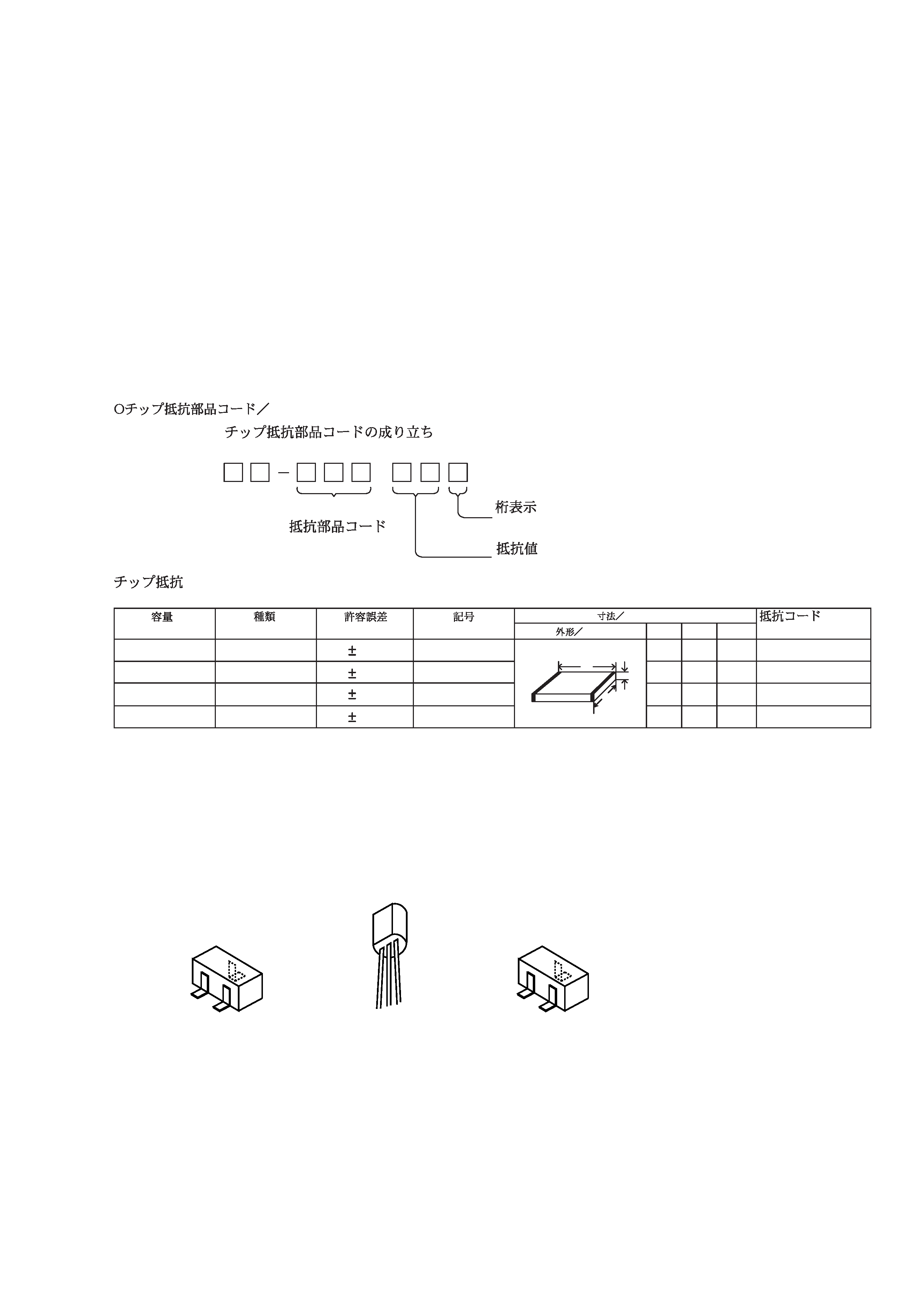
TRANSISTOR ILLUSTRATION
MOTOR C.B
PIN3
91-564-722-110
CONN,PIN 6P
SW1
91-572-085-110
LEAF SWITCH
·
Regarding connectors, they are not stocked as they are not the initial order items.
The connectors are available after they are supplied from connector manufacturers upon the order is received.
88
A
Resistor Code
Chip Resistor Part Coding
Figure
Value of resistor
Chip resistor
Wattage
Type
Tolerance
1/16W
1/10W
1/8W
1608
2125
3216
5%
5%
5%
CJ
CJ
CJ
Form
LW
t
1.6
0.8
0.45
2
1.25
0.45
3.2
1.6
108
118
128
: A
: A
CHIP RESISTOR PART CODE
0.55
Resistor Code
Dimensions (mm)
Symbol
1/16W
1005
5%
CJ
1.0
0.5
0.35
104
L
t
W
G
S
D
B
EE C B
C
2SK2158
2SA1235F
2SC3052F
DTC124XK
DTC144TK
KTA1266GR