SERVICE MANUAL
STEREO CAR
CD CHANGER SYSTEM
BASIC CD MECHANISM : 8ZG-4 RNF
ADC-EX108
ADC-M105
YZ
YL,YH
S/M Code No. 09-003-404-5R7
REVISION
· This Service Manual is the "Revision Publishing" and replaces "Simple Manual",
(S/M Code No. 09-003-404-5T7).
DA
TA

SPECIFICATIONS
ACCESSORIES / PACKAGE LIST
DESCRIPTION
REF. NO.
KANRI
NO.
PART NO.
- 2 -
<Compact disc changer>
System
Compact disc digital audio system
Frequency Response
5 Hz - 20 kHz
Wow and flutter
Below measurable limit
Signal to noise ratio
91 dB or more
Outputs
Line output (for changer connector only)
Operating temperature
-10 oC to 55 oC
Dimensions
254 x 83 x 173mm (w/h/d)
(10 x 3 3/
8 x 6
7/
8 in.)
Weight
2.1 kg (4.62 lbs.)
Power requirement
12 V DC car battery
(negative ground)
D/A converter
1 bit DAC, 8 times over sampling
Sampling rate
44.1 kHz
Disc size
120 mm
· Design and specifications are subject to change without notice.
1
8Z-KM3-914-010
IB,YL(3L) M105-I<YL>
1
8Z-KM3-915-010
IB,YZ(9L) 108,M105-I<YZ>
1
8Z-KM3-916-010
IB,YH,Y(E CK CH A) 108M105-I<YH>
2
87-B10-208-010
VWWS+4-12 BLK
3
8Z-KM1-210-110
PLATE,UNIT ASSY
4
8Z-KM1-218-010
NUT,5 HEX-FLANGE
5
8Z-KM1-209-010
HLDR,UNIT 10A
6
8Z-KM1-216-010
HLDR,UNIT 10B
7
8Z-KM4-651-010
CABLE ASSY,13PIN-DIN
3
CLASS 1
LASER PRODUCT
KLASSE 1
LASER PRODUKT
LUOKAN 1
LASER LAITE
KLASS 1
LASER APPARAT
This set employs laser. Therefore, be sure to follow carefully
the instructions below when servicing.
WARNING!!
WHEN SERVICING, DO NOT APPROACH THE LASER
EXIT WITH THE EYE TOO CLOSELY. IN CASE IT IS
NECESSARY TO CONFIRM LASER BEAM EMISSION.
BE SURE TO OBSERVE FROM A DISTANCE OF MORE
THAN 30cm FROM THE SURFACE OF THE OBJEC-
TIVE LENS ON THE OPTICAL PICK-UP BLOCK.
s Caution: Invisible laser radiation when
open and interlocks defeated avoid
exposure to beam.
s Advarsel: Usynlig laserståling ved åbning,
når sikkerhedsafbrydere er ude af funktion.
Undgå udsættelse for stråling.
VAROITUS!
Laiteen Käyttäminen muulla kuin tässä käyttöohjeessa
mainitulla
tavalla
saataa
altistaa
käyt-täjän
turvallisuusluokan 1 ylittävälle näkymättömälle
lasersäteilylle.
VARNING!
Om apparaten används på annat sätt än vad som
specificeras i denna bruksanvising, kan användaren
utsättas för osynling laserstrålning, som överskrider
gränsen för laserklass 1.
PROTECTION OF EYES FROM LASER BEAM DURING SERVICING
CAUTION
Use of controls or adjustments or performance of proce-
dures other than those specified herin may result in
hazardous radiation exposure.
ATTENTION
L'utillisation de commandes, réglages ou procédures
autres que ceux spécifiés peut entraîner une dangereuse
exposition aux radiations.
ADVARSEL
Usynlig laserståling ved åbning, når sikkerhedsafbrydereer
ude af funktion. Undgå udsættelse for stråling.
This Compact Disc player is classified as a CLASS 1
LASER product.
The CLASS 1 LASER PRODUCT label is located on the
rear exterior.
PICK-UP ASSY
P.C.B
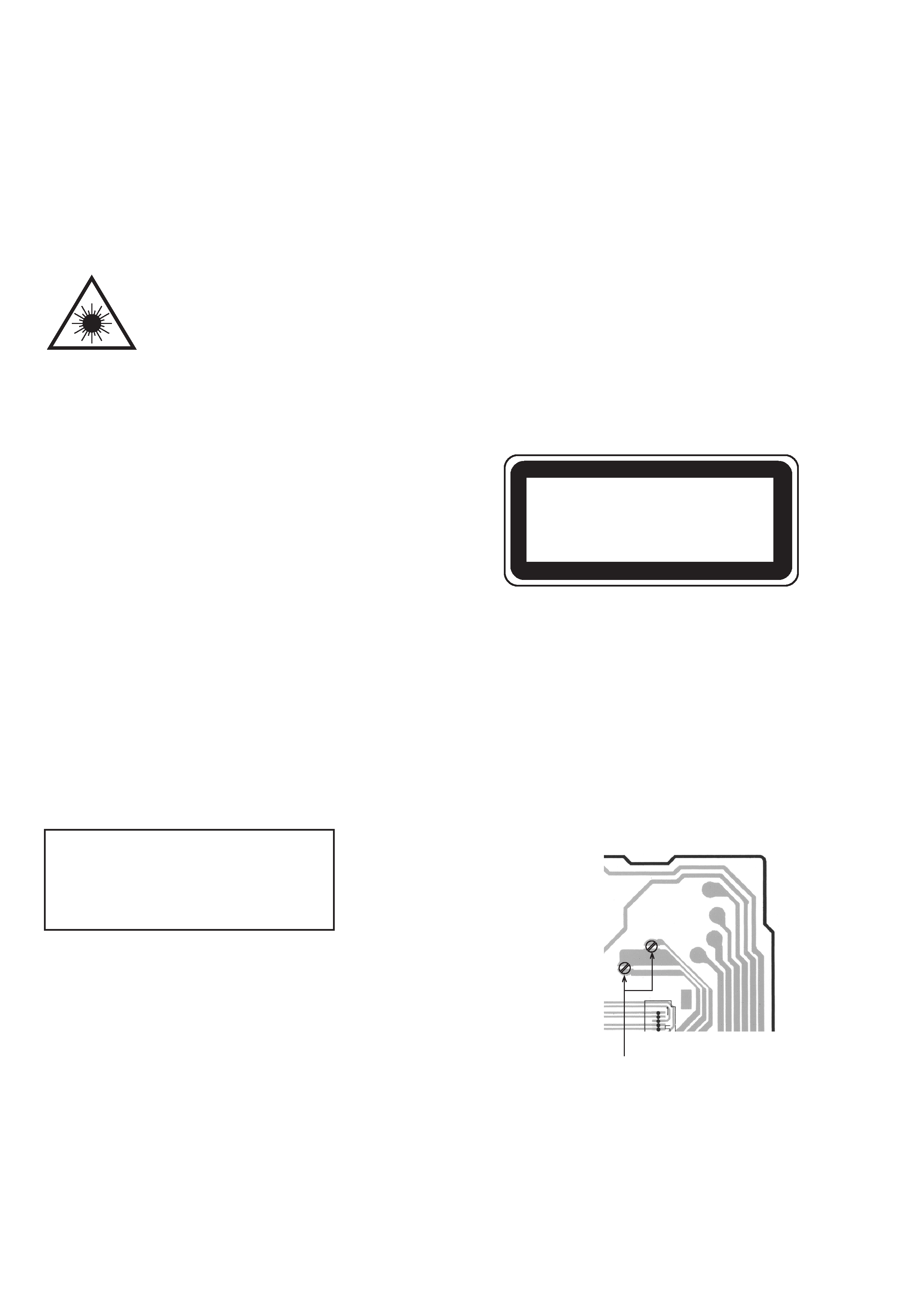
Precaution to replace Optical block
(KSS-710A)
Body or clothes electrostatic potential could
ruin laser diode in the optical block. Be sure
ground body and workbench, and use care the
clothes do not touch the diode.
1) After the connection, remove solder shown in
right figure.
SOLDER
- 4 -
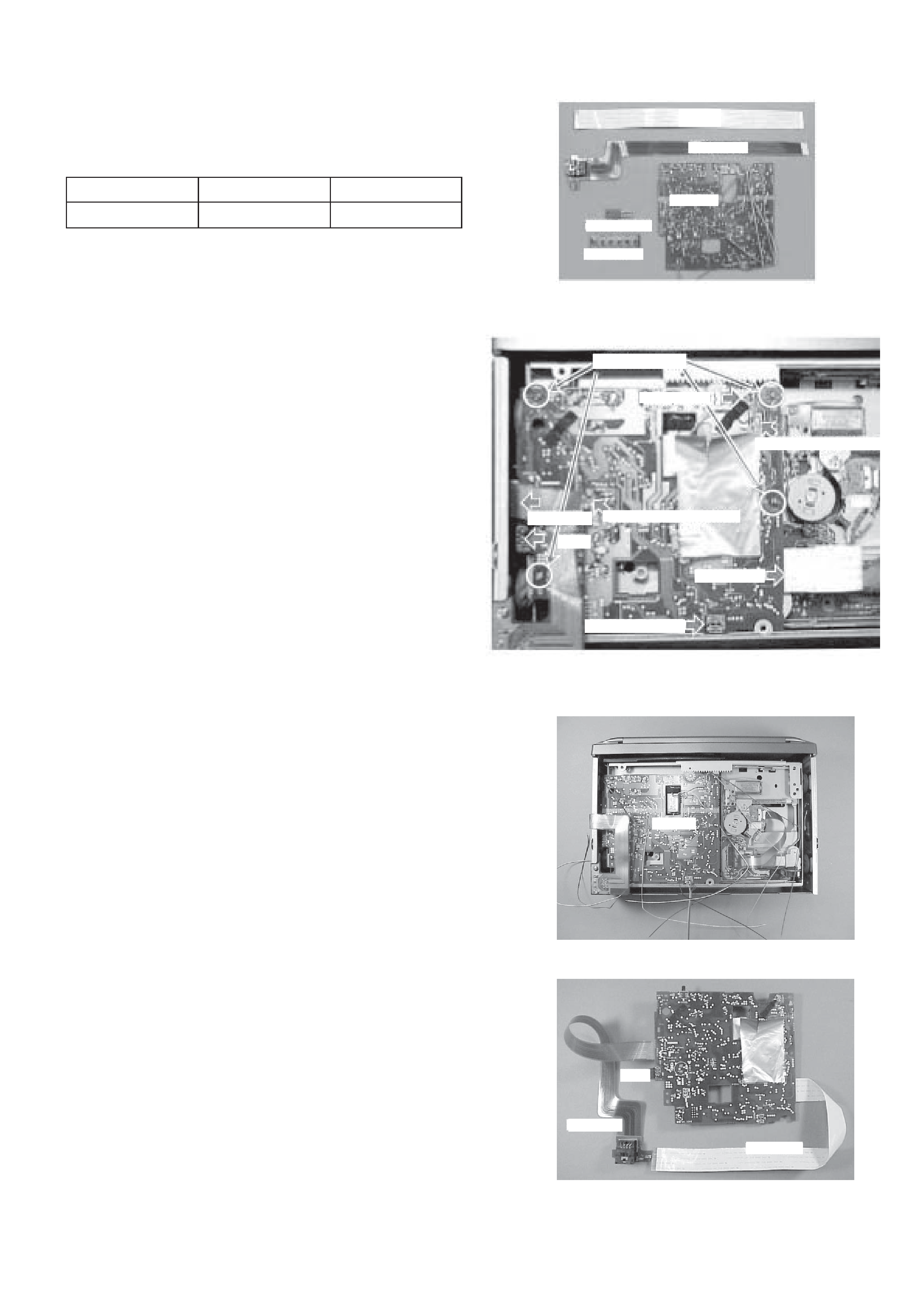
1. How to Use the Repair Jig
Use the following repair jig kit for servicing.
The kit contains the following parts (Refer to Fig-1) ;
1.
FFC (26P/25 cm)
1 pcs
2.
P.W.B. FLEX
1 pcs
3.
P.W.B. JIG
1 pcs
4.
TRANSISTOR (2SD-2395)
1 pcs
5.
P.W.B. KEY
1 pcs
(1)
Remove the cabinet as follows;
1)
Remove the CABI BOTTOM by removing the
four screws VTT+2.6-6B (Refer to Fig-2).
(2)
Remove the P.W.B. MAIN as follows;
1)
Remove all terminals of the transistor Q623
(2SD2395) by unsoldering them.
2)
Remove the two motor wires (BLU/WHT).
3)
Remove the two wires (BLK/BRN) of the sensor
(PD201).
4)
Remove the P.W.B. MAIN from the unit by
removing the four screws V+2-3.
5)
Disconnect the FFC of pickup from CN101.
6)
Disconnect the PWB FLEX from CON1.
7)
Remove the LED (LED201,GL380) from the
P.W.B. MAIN.
8)
Remove the sensor (PS201,SENR GP1S94) from
P.W.B. MAIN.
(3)
Install the repair jig as follows;
1)
Install the P.W.B. JIG into the unit and fix it with
screws. (Refer to Fig-3).
(4)
Attach the parts as follows, (Refer to Fig-4);
1)
Attach the supplied transistor to the location of the
P.W.B. MAIN from which Q623 is removed in
step (2).
2)
Connect the supplied PWB FLEX to CON1.
· When the CONTROL UNIT is not used, use the
P.W.B. KEY instead. (Refer to step (6), How to
use the repair jig.)
3)
Connect the FFC cable to CON101 and pickup.
(The supplied FFC cannot be used because pitches
and number of pins are different.)
SERVICE JIG AND TOOLS
Part name
Part code
For 10 CD changer
JIG-ADC-EX106
SV-J00-090-010
Fig-1
Fig-2
Fig-3
Fig-4
FFC
FFC
TRANSISTOR
PWB KEY
REMOVE SCREW
LED(LED201)
REMOVE MOTOR WIRE
PWB FLEX
REMOVE SENSOR WIRE
Q623
PICKUP FCC
SENSOR (PS201)
PWB JIG
Q623
PWB FLEX
FFC CABLE
PWB JIG
- 5 -
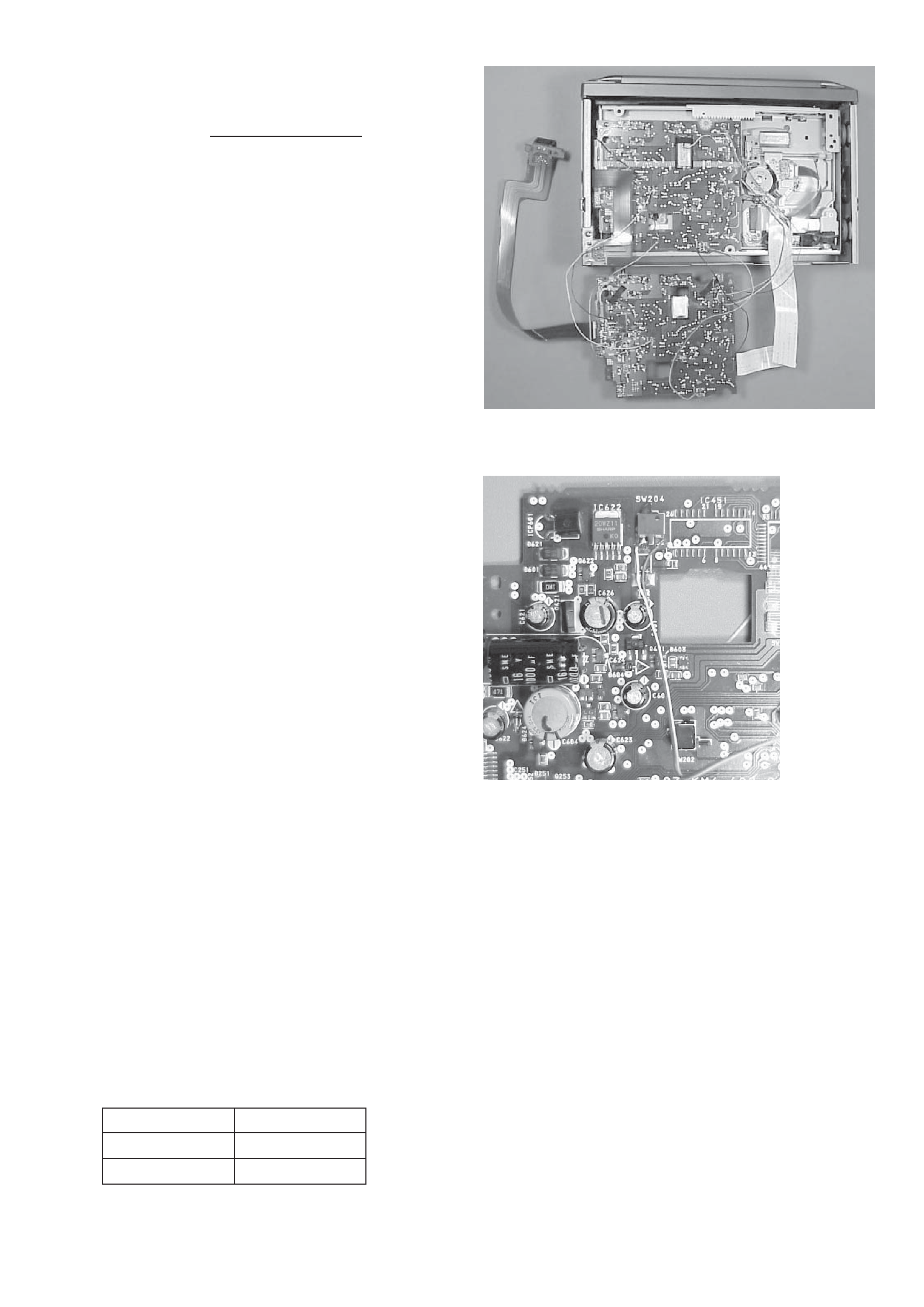
Fig-5
Fig-6
(5)
Perform wirings to the C.Bs. Refer to Fig-5/-6;
·
Be sure to connect the wires coming from the
P.W.B. JIG to the same connecting points on the
MAIN C.B as follows.
1)
Connect the motor wires and sensor (PD201)
wires that are removed in step (2) to the P.W.B.
JIG.
2)
Connect all wires coming from the P.W.B. JIG to
the respective lands of the MAIN C.B by
soldering.
·
Connect the motor wires (BLU/WHT) of the
P.W.B. JIG to the motor wire connecting lands on
the MAIN C.B by soldering.
·
Connect the LED (LED201) wires (RED/GRY) of
the P.W.B. JIG to the LED wire connecting lands
on the MAIN C.B by soldering.
·
Connect the sensor wires (BRN/BLK) of the
P.W.B. JIG to the sensor wire connecting lands on
the MAIN C.B by soldering.
·
Connect the sensor (PS201) wires (YEL/ORG/
RED/BRN) of the P.W.B. JIG to the sensor wire
connecting lands on the MAIN C.B by soldering.
·
Connect the SW202 wire (WHT) of the P.W.B.
JIG to the SW202 wire connecting lands on the
MAIN C.B by soldering.
·
Connect the SW203 wire (BLK) of the P.W.B.
JIG to the SW203 wire connecting lands on the
MAIN C.B by soldering.
·
Connect the SW204 wires (BLU/WHT) of the
P.W.B. JIG to the leads of SW204 on the MAIN
C.B by soldering. Refer to Fig-6.
(6)
How to use the repair jig;
When the Control Unit (CDC/CT) is going to be used.
1)
After all wires and connections are complete,
connect the Control Unit (CDC/CT) with the DIN
jack of the P.W.B. FLEX.
2)
Connect external power +12 V to ACC/BACKUP
wire and ground (-) to the GROUND wire.
3)
Perform the operation check.
When the Control Unit (CDC/CT) is not used.
1)
Connect the supplied P.W.B KEY to the MAIN
C.B by performing all connections between them.
Refer to Fig-7/-8.
(Wires to be used for connecting the MAIN C.B
are not supplied.)
2)
Connect the wires as follows. Refer to Fig-9.
P.W.B KEY
MAIN C.B
HOT
TO
GND
GND